Table of Contents
Advertisement
Quick Links
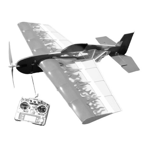
Skeeter 40
Electric 3D Aerobatic Model Airplane Kit
Instruction Manual
READ THROUGH THIS MANUAL BEFORE STARTING CONSTRUCTION. IT CONTAINS IMPORTANT INSTRUCTIONS AND
WING SPAN
WING AREA
LENGTH
WEIGHT RTF
MOTOR
WARNINGS CONCERNING THE ASSEMBLY AND USE OF THIS MODEL.
40 in
40 in
28-44oz.
Torque 2818T/900
1
Advertisement
Table of Contents

Summary of Contents for QUINN Skeeter 40
- Page 1 Skeeter 40 Electric 3D Aerobatic Model Airplane Kit Instruction Manual WING SPAN 40 in WING AREA LENGTH 40 in WEIGHT RTF 28-44oz. MOTOR Torque 2818T/900 READ THROUGH THIS MANUAL BEFORE STARTING CONSTRUCTION. IT CONTAINS IMPORTANT INSTRUCTIONS AND WARNINGS CONCERNING THE ASSEMBLY AND USE OF THIS MODEL.
-
Page 2: Table Of Contents
They will teach you how to set up your flyability of your finished model depends on how you build it. plane properly, and turn you into a great 3D pilot. COPYRIGHT © 2005 Join here: The Profile Brotherhood Quinn Coldiron http://www.theprofilebrotherhood.com qcoldir@yahoo.com... -
Page 3: Decisions You Must Make
1 , then glued as a single unit 1 – 2 rolls of covering material Covering iron and heat gun #1 Hobby Knife Handle #11 Blades © 2005 Quinn Coldiron All rights reserved. For additional information, please contact: www.billyhellrc.com... -
Page 4: Wing Build
Wing Build After the endcap rib is glued on, glue the trailing edge 1/4x1/8 stock strip to the trailing edge of the wing. Glue the entire long strip on, then trim it when the glue The first step is to join the spar at the center. Butt sets. - Page 5 Add the 1x4 balsa square center reinforcement stick.
- Page 6 Using 1/16 sheeting, sheet the center section of the wing. The grain should run the length of the cord, except for the leading edge, which runs span wise for easy bending around the leading edge. Cut the wing sheeting parts from the center of the fuse sheeting laser cut parts.
-
Page 7: Aileron Build
Aileron Build Find and lay out the laser cut pieces of the 2 ailerons. They will be built one at a time. Cut all the sticks now, fit them together and glue. Repeat for the other aileron. Glue the tri-stock to the leading edge of the ailerons only.. - Page 8 HStab, Elevator and Rudder Build HStab and Elevator Rudder Cut the sticks to length, according to the printed plans, As with the other tail surfaces, cut the sticks to length, then lay the laser cut parts out on the plans, fitting the according to the printed plans, then lay the laser cut sticks into the pre-cut slots.
-
Page 9: Fuselage Build
Fuselage Build Note: Take 2 of the ¼ inch balsa square sticks, cut to the length of the long fuse. The lower stick will need The canopy is formed by wetting a 1/8x1/4 balsa stick to be joined together. Please look at the printed with a damp cloth until it bends easily. - Page 10 Next up is the fuse sheeting. If building the electric version, use the balsa sheeting. If building the glow version, use the ply sheeting. If you are using a stick style electric motor, then just sheet the nose, everything is ready for you. If using an outrunner, then cut away the needed area from the nose.
-
Page 11: Final Assembly
Final Assembly and Covering I will not talk in detail on how to cover your plane. Many online resources can be found, and many different covering materials are available. I do recommend that you cover the individual pieces before the final assembly. After covering the pieces it is time to mount the wing and horizontal stabilizer. -
Page 12: Motor Installation
Option #2: Motor-on-a-stick Motor Installation Motor Installation The electric motor installation is shown below. Fill in the nose area with scrap balsa. Take 2 hardwood sticks and glue them together, then slid that into the slot in the nose, setting the desired right thrust. The airplane was originally designed around a motor-on-a-stick Bolt the gearbox and motor to the stick, with the motor hanging off the system, but has been changed to an outrunner mount. -
Page 13: Radio Installation
Balance Your Model Radio Installation The battery is simply attached to the side of the fuselage with sticky- back Velcro tape. The location depends on the components and The radio and battery are placed in the open battery box in the wing battery you are using.
Need help?
Do you have a question about the Skeeter 40 and is the answer not in the manual?
Questions and answers