
Subscribe to Our Youtube Channel
Related Manuals for Xaoc Devices DREZNO


Summary of Contents for Xaoc Devices DREZNO
- Page 1 binary conversion komputor & bit inversion commander Models of 1989 operator’s manual rev. 1989/1.0...
- Page 2 ). For example, a 3-bit code can represent the values 0 (code 000), 1 (code 001), Drezno and Lipsk are the first in series of modules 2 (code 010), 3 (code 011) ... up to 7 (code 111). In which constitute The Leibniz Binary Subsystem, a...
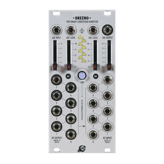
- Page 3 front panel overview fig. 1...
- Page 4 LEVEL • When patched 1:1 (or linked without any modifi- cations), processing of signals and voltages through ADC+DAC of Drezno results in a subtle 8-bit quanti- zation effect. Modifying the binary representation creates various discontinuities in the transfer func- tion, depending on which bits are affected.
- Page 5 MADE IN THE EU rate reduction when using an external clock. XAOCDEVICES.COM • Drezno (with or without Lipsk connected) can be • Generating trigger patterns: feeding an LFO or a se- used in combination with other logic modules (like quencer into the ADC provides trigger patterns useful AND, OR, XOR, etc.), operating on individual bits...
- Page 6 binary conversion converter clock for clarity, only four most significant bits are shown input saw wave and significance of individual bits result of leaving only the most significant bit (7) result of leaving three most significant bits (7, 6, 5) gate signals at individual bit outputs result of inverting the most significant bit (7) only result of inverting bit (6) only...
- Page 7 fig. 4: input sinusoidal signal and individual binary gates result of four most significant bits (7, 6, 5, 4) fig. 5: input sawtooth signal and individual binary gates result of inverting two most significant bits (7, 6) replacement of bit (7) by external gate and omission of bit (6)
- Page 8 WaRRaNty tERmS XAOC DEVICES WARRANTS THIS PRODUCT TO BE FREE OF DEFECTS IN MATERIALS OR WORKMANSHIP, Universal AND TO CONFORM WITH THE SPECIFICATIONS AT THE TIME OF SHIPMENT FOR A PERIOD OF ONE YEAR subsystem for FROM THE DATE OF PURCHASE. DURING THAT PERIOD ANY MALFUNCTIONING OR DAMAGED UNITS creating and WILL BE REPAIRED, SERVICED, AND CALIBRATED ON A RETURN-TO-FACTORY BASIS.
Need help?
Do you have a question about the DREZNO and is the answer not in the manual?
Questions and answers