Advertisement
Quick Links
Advertisement

Subscribe to Our Youtube Channel
Related Manuals for marklin HO


Summary of Contents for marklin HO
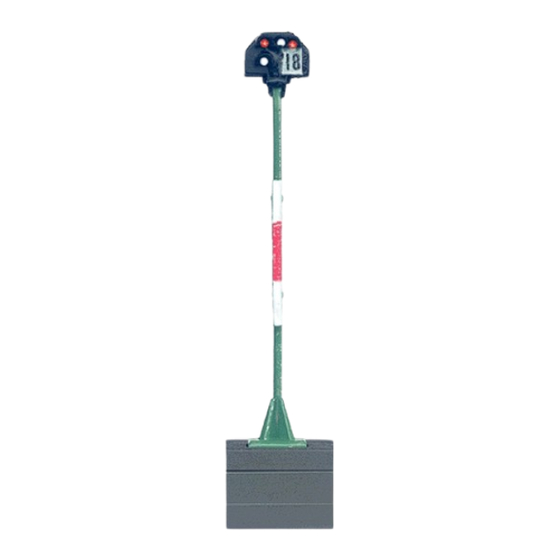
- Page 1 入換信号機 地上型・マスト型 76371/76372...
- Page 2 • When the signal is set at „slow“, the operator is ピードを落とす必要があります(信号機により自動 responsible for adjusting the speed of the train. で減速されません)。 • The signal control module can only be used • 同梱の制御モジュールは、メルクリン製HOスケー to control signals from the Märklin series that ルデジタル色灯信号機の制御専用です。他のシ belong to it. リーズの信号機や他社の信号機の制御には使用...
- Page 3 実際の信号機の現示 Aspects in the Prototype 入換信号機の現示: Signal indication of the platform blocking signal: 停止 入換進行 意味: Stop Meaning: Allowed...
- Page 4 センターレールへの給電: Track Current: オン オフ...
- Page 5 デジタルアドレスの設定 Setting the Digital Address Important: No address needs to be set for con- 重要:アナログ制御時は、アドレス設定は不要です。 ventional wiring connections General Information: 概要: • プログラミングピン(ボール紙にはさまれた針金状のも • The address can be set only when the signal control module with the signal mast connect- の)を差し込んだ信号制御モジュールに信号機を接続...
- Page 6 Button Assignment on the Keyboard: 入換信号機のアドレス: 1つのアドレスが必要で、Keyboardでは、1組のボタ Track block signal: 1 key pair on keyboard ンに割り当てます。 Control button assignment on the Central Station: Please see the instructions for the Central Sta- 準備: tion about this topic. 6040 Keyboardの場合は、設定したいアドレスの ボタンをすぐ押せるようにしておきます。 Example: 例えば、ここでは入換信号機を1番キーボードの...
- Page 7 アドレス設定手順 Procedure for Entering the Address 1. 6021と6040 もしくは Central Stationと、トランスや 1. Connect the Control Unit, Keyboard, and ACアダプターを接続します。まだ電源コードをコン transformer. Do not turn the Control Unit on セントに差し込まないでください。 yet. 2. 信号機を接続した信号制御モジュールにプログラ 2. Leave the signal control module with con- ミングピン(ボール紙にはさまれた針金状のもの)を nected main signal mast in the blister package 差し込みます。信号制御モジュールの黄色と茶色...
- Page 8 6. Press the green button on button pair 3 of the 6. Keyboardのアドレス3の緑ボタンを押し始めます。 Keyboard until all of the LED‘s on the signal Central Stationの場合は、信号機をタッチし、 light up. Only release the button at this point. Sh1(白、進行)にします。すると、信号機のすべての 7. Turn the Control Unit off. The signal and the LEDが点灯します。Keyboardの場合は、ここで緑ボ...
- Page 9 Note: 注意: • For long breaks during programming, the • 設定中に作業を30秒以上止めると、信号機はアド signal terminates the programming mode レス設定モードを終了してしまいアドレスも設定さ without a change. In this case, start from the れません。その場合は、手順を最初からやり直し beginning again with the complete addressing てください。アドレス設定中は、各動作に時間をか procedure. While addressing is taking place, けすぎないようにしてください。...
- Page 10 アナログ制御時の配線図 Conventional Wiring Connections 72720 72720...
- Page 11 デジタル制御時の配線図 Digital Wiring Connections 6021 + 6040 または 60212/3/4/5 6021 + 6040 60212/3/4/5...
- Page 12 制御モジュールのCレールへの取付け Signal Control Module Installed in C Track...
- Page 13 制御モジュールのレイアウトボード下への取付け Signal Control Module Installed under the Layout...
- Page 14 信号マストブラケットの取付け Mounting Brackets for Signal Masts 重要:信号機接続基板には方向性 があります。切り欠き部を台座と 合わせて下さい! Important: The wiring connections board can only be installed in one direction!
- Page 15 信号マストの取付け 重要:信号マストは台座に対し一方向のみからしか取付けられません。 Installing the Signal Mast. Important: The signal mast can only be installed in one direction.
- Page 16 3〜5%の上り坂・下り坂で信号マストを垂直に保ちます。 Level out an Ascending or Descending Grade at a Signal Mast (3% or 5%)
- Page 17 架線の接続 Additional Feeder Contact for Catenary 架線集電で、赤信号時に列車を自動で止めたい場合は、 図のソケットにフィーダー線を接続し ます。フィーダー 線の接続の方法は、6ページの線路への接続と同じです。すなわち、上の赤 線をコントローラーの赤線(B)へ、 下の赤線をストップ区間の架線マストへ接続します。ストップ 区間と通常区間は絶縁用架線により絶縁することを忘れないでください。...
- Page 18 この製品はFCCルール のPart15に準拠していますが、使用に際して は以下の2つ の制約を受けることがあります: (1)他のシステムに有害な電磁妨害を引き起こしてはならない。かつ、 (2)他のシステムから、不正動作を引き起こす可能性のある電磁妨害 を受ける可能性がある。 This device complies with Part 15 of the FCC Rules. Operation is subject to the following two conditions: (1) This device may not cause harmful interference, and (2) this device must accept any interference received, including interference that may cause undesired operation.
Need help?
Do you have a question about the HO and is the answer not in the manual?
Questions and answers