
Related Manuals for TELEDYNE OLDHAM SIMTRONICS Everywhereyoulook MultiFlame DF-TV7


Summary of Contents for TELEDYNE OLDHAM SIMTRONICS Everywhereyoulook MultiFlame DF-TV7
- Page 1 OPERATING MANUAL MULTIFLAME DF-TV7 OPTICAL FLAME DETECTOR DF-TV7-T Multi-spectrum IR DF-TV7-V Combined UV/IR (with Magnetic interface) NOSP17662-Revision 03...
- Page 2 User Manuals in other languages are available on Website https://teledynegasandflamedetection.com Copyright March 2021 by TELEDYNE OLDHAM SIMTRONICS S.A.S. All rights reserved. No reproduction of all or part of this document, in any form, is permitted without the written consent of TELEDYNE OLDHAM SIMTRONICS S.A.S.
- Page 3 SIMTRONICS, even though they may be involved in the sale of TELEDYNE OLDHAM SIMTRONICS products. TELEDYNE OLDHAM SIMTRONICS shall not be responsible for any direct or indirect damage, or any direct or indirect consequence, resulting from the sale and use of any of its products UNLESS SUCH PRODUCTS HAVE BEEN SELECTED BY TELEDYNE OLDHAM SIMTRONICS ACCORDING TO THE APPLICATION.
- Page 4 The use of the unit has been projected for the applications specified in the technical characteristics. Exceeding the indicated values cannot in any case be authorized. TELEDYNE OLDHAM SIMTRONICS recommends regular testing of fixed gas detection installations (read Chapter 7).
-
Page 5: Table Of Contents
MULTIFLAME DF-TV7 OPTICAL FLAME DETECTOR OPERATING MANUAL Table of Contents 1 Product Description ................1 Applications ......................1 DF-TV7-T: multi-spectrum IR ................2 DF-TV7-V: combined UV and IR ..............2 Technical specifications ................. 2 Detection Cartridge ..................3 Optical self-test function ................4 Communication Interface ................ - Page 6 MULTIFLAME DF-TV7 OPTICAL FLAME DETECTOR OPERATING MANUAL Power and fault indications ................33 Alarm indication (LED) ..................33 Wireless communication tool TLU600 ............34 Information menu [INFO] ................37 Adjustment menu [ADJT] ................38 The maintenance menu [MAIN] ..............41 6.10 Magnets Operation ..................
-
Page 7: Product Description
MULTIFLAME DF-TV7 OPTICAL FLAME DETECTOR OPERATING MANUAL Product Description MultiFlame DF-TV7-T was designed to detect hydrocarbon fires, while minimizing false alarms. This detector is equipped with an intelligent optical self-test. It is certified and may be installed in SIL2 level system. It can be directly connected to a wide range of traditional or fire controllers and on Programmable Logic Controllers (PLC). -
Page 8: Df-Tv7-T: Multi-Spectrum Ir
MULTIFLAME DF-TV7 OPTICAL FLAME DETECTOR OPERATING MANUAL DF-TV7-T: multi-spectrum IR The DF-TV7-T is a multi-spectrum flame detector using three individual infrared wavelengths. The use of three different IR bands and a unique signal processing algorithm allows excellent flame detection performances, while offering a very low rate of false alarms. -
Page 9: Detection Cartridge
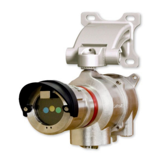
MULTIFLAME DF-TV7 OPTICAL FLAME DETECTOR OPERATING MANUAL Figure 1 : Detector presentation (Overall dimension drawings, see Figure 2) Detection Cartridge Cartridges are explosion proof designed. They are common to all MultiFlame line of products in order to reduce spares parts. •... -
Page 10: Optical Self-Test Function
MULTIFLAME DF-TV7 OPTICAL FLAME DETECTOR OPERATING MANUAL Optical self-test function Sensor cartridges have one or more self-test optical lamps allowing detection integrity test. This is a full optical test where the signal from each test lamp is transmitted through the sensor window and reflected back to the detecting elements via a polished stainless-steel reflector. - Page 11 HART protocol is optional. Read the P/N on your detector and check it contains the letter ‘H’ at the 12th position for HART compatibility. P/N: DF-TV7-****- **H-**-***-*-*-* TELEDYNE OLDHAM SIMTRONICS devices under HART protocol enable the use of all the functions available with the TLU600 via the HART terminal Read document P/N D1401002 for Hart Terminal TLH700 operation (Device Descriptor file must be downloaded).
-
Page 12: Product Code
MULTIFLAME DF-TV7 OPTICAL FLAME DETECTOR OPERATING MANUAL Product Code ξ σ αβ ρ ε µ φ V7-X# Product codes are created from functional codes: σ ξ α β ρ ε µ φ Compact capteur Télécapteur Capteur réseau / Network version Famille / Families Flamme / Flame Génération... -
Page 13: Technical Features
MULTIFLAME DF-TV7 OPTICAL FLAME DETECTOR OPERATING MANUAL Technical features GENERAL Type Optical flame detectors DF-TV6-T Multi-spectrum IR Flame detector DF-TV7-V Combined IR and UV detection. Start-up time 15 secs Self-test Automatic periodic test through the window Calibration Factory set, no field recalibration OUTPUT SIGNAL 4-20mA loop signal Active type (source), max. - Page 14 MULTIFLAME DF-TV7 OPTICAL FLAME DETECTOR OPERATING MANUAL ELECTRICAL Power supply 24V DC,(Range 18 – 35 V DC versions DF-T#7) (Range 18 – 30 V DC versions DF-R#7) Power consumption UV2IR Typical 1.4w 1.5 w network : 2.6 w network : 2.7W Maximum Connection 0,5mm²...
- Page 15 MULTIFLAME DF-TV7 OPTICAL FLAME DETECTOR OPERATING MANUAL FONCTIONNAL SAFETY SIL certification in progress according IEC/EN 61508 parties 1 to 7 standard Values Value relay Detector Data Definitions current output output λ Failure rate per hour 1.57x10 1.53x10 Multi IR Safety fraction failure 99.2% 92.5% DF-TV7-T...
- Page 16 MULTIFLAME DF-TV7 OPTICAL FLAME DETECTOR OPERATING MANUAL DIMENSIONS Figure 2 : Dimension drawings NOSP17662 Revision 03...
-
Page 17: Performances
MULTIFLAME DF-TV7 OPTICAL FLAME DETECTOR OPERATING MANUAL Performances Sensitivity 3.1.1 Fire class Classification according to §5.5.3 – EN 54-10 (2006), (ethanol and n-heptane fires) DF-TV7-XVA0 ET DF-TV7-XTA0 Sensitivity 100% Time delay Class 2 Class 1 Class 1 Max (20 sec) Class 2 Class 2 Class 1... -
Page 18: Field Of View (Cone Of Vision)
MULTIFLAME DF-TV7 OPTICAL FLAME DETECTOR OPERATING MANUAL Field of View (Cone of Vision) DF-TV7-XTA0 DF-TV7-XVA0 DF-TV7-XTB0 α : Maximum angle as defined in standard EN 54- 30° 35° 10 (2006) - § 5.4 Angle at 50% sensitivity Horizontal total 97° 104°... -
Page 19: False Alarm Immunity (Fm 3260)
MULTIFLAME DF-TV7 OPTICAL FLAME DETECTOR OPERATING MANUAL DF-TV7-XTA0 and DF-TV7-XTB0 Typical horizontal detection: Typical vertical detection: False alarm immunity (FM 3260) XTA0 (IR3) XTB0 (IR3) Distance XVA0 (UVIR²) Standard m (ft.) Long range range 100 % / 2 sec Modulated / 75 % / 5 sec 100% / 5 sec (fact. - Page 20 MULTIFLAME DF-TV7 OPTICAL FLAME DETECTOR OPERATING MANUAL NOSP17662 Revision 03...
-
Page 21: Installation
MULTIFLAME DF-TV7 OPTICAL FLAME DETECTOR OPERATING MANUAL Installation The detector must be installed in accordance with its certification and with the standards of the appropriate authority in the country concerned. Location The detector should be positioned above the targeted danger zone and at a distance corresponding to the type of fire it has to detect. -
Page 22: Mounting
MULTIFLAME DF-TV7 OPTICAL FLAME DETECTOR OPERATING MANUAL Mounting Use the two 7 mm diameter holes and the half-slotted hole to secure the support. It is highly recommended to install the support with cable-gland downward in order to avoid water infiltrations. In case of horizontal position, it is advised to make one or two loops with the cable at the entry of the cable-gland. - Page 23 MULTIFLAME DF-TV7 OPTICAL FLAME DETECTOR OPERATING MANUAL Start by fixing the base support. The adjustment and termination of cables are performed into the base only. This limits the exposure of the electronic components in the housing to a minimum. 4.2.1.2 Ball pivot bracket – AS048 The detector is supported by a completely adjustable support.
- Page 24 MULTIFLAME DF-TV7 OPTICAL FLAME DETECTOR OPERATING MANUAL 4.2.3 Sunshade / bad weather protection A sunshade / weather protection (AS056-450) in light and resistant material (UV resistant) is available. Mounted above the detector, it gives an additional protection against sun and bad weather.
-
Page 25: Electric Connection
MULTIFLAME DF-TV7 OPTICAL FLAME DETECTOR OPERATING MANUAL 4.2.6 Cable‘s inputs (as an option) Connection cables must pass through a cable gland (Explosion Proof certified) For installation details, refer to the instructions provided by the manufacturer of the cable gland used. The unassigned cable glands entries must be blanked with explosion proof certified plugs (M20). - Page 26 MULTIFLAME DF-TV7 OPTICAL FLAME DETECTOR OPERATING MANUAL 4.3.1 Connection of the electrical ground braid Use a shield connection clamp (not supplied) to connect the shielding of the cable to the electric ground of the housing (see below). 4.3.2 Grounding A M4 screw passes through the body of the enclosure, enabling the electronic ground of the housing to be connected to the local ground.
- Page 27 MULTIFLAME DF-TV7 OPTICAL FLAME DETECTOR OPERATING MANUAL Terminal blocks : Point JP11 Description 0 V retour +24VDC power supply +24VDC power supply loop (connected to point 2) 0 V, connected to point 1 20mA current loop : entry 20mA current loop : output 4.3.3.1 3-wires connection (source) Detector JP11...
- Page 28 MULTIFLAME DF-TV7 OPTICAL FLAME DETECTOR OPERATING MANUAL In this case, the output current is not isolated from power supply, consumed by the detector. The 20mA current loop must be supplied with a PLC. The current return must be connected to the 0V at the level of the L- terminal.
- Page 29 MULTIFLAME DF-TV7 OPTICAL FLAME DETECTOR OPERATING MANUAL Relay card, terminal block (option): Point Description Relay1 common Relay 1 de-energized Relay 1 energized Relay 1 energized Relay 2 common Relay 2 common Relay 2 de-energized Relay 2 energized Relay 2 energized Relay 3 common Relay 3 de-energized Relay 3 energized...
- Page 30 MULTIFLAME DF-TV7 OPTICAL FLAME DETECTOR OPERATING MANUAL Maintain a 10mm minimum gap between the resistor and the terminal block or any other neighboring parts. The recommended connections are indicated below: The R1 value is given as an indication. It must comply with the following conditions: •...
-
Page 31: Detection Cartridge
MULTIFLAME DF-TV7 OPTICAL FLAME DETECTOR OPERATING MANUAL Connecting the ground terminal should be performed thanks to 3-wire shielded cables. The connection of power supply wires (4 on side A and 4 on side B). • Two red wires on V +: +24 V •... - Page 32 MULTIFLAME DF-TV7 OPTICAL FLAME DETECTOR OPERATING MANUAL Be careful when plugging or removing the detection cartridge. • Align the centring pin of the cartridge with the corresponding hole in the housing. • Insert the cartridge in the bell, holding the two parts as parallel as possible.
- Page 33 MULTIFLAME DF-TV7 OPTICAL FLAME DETECTOR OPERATING MANUAL Switches S1 and S2 are used for the UV/IR detection mode as shown in the table below. The configuration is frozen and cannot be changed with the TLU. Switches S1 and S2 are not used for the multi-spectrum sensor cartridges (3IR).
- Page 34 MULTIFLAME DF-TV7 OPTICAL FLAME DETECTOR OPERATING MANUAL NOSP17662 Revision 03...
-
Page 35: Commissioning
MULTIFLAME DF-TV7 OPTICAL FLAME DETECTOR OPERATING MANUAL Commissioning Visual inspection Make certain that all the operations of the “Installation” chapter have been achieved correctly. Pay particular attention on installation conformity, check the cables entry, the presence of O- rings, and the connexion of the cartridge. •... -
Page 36: Using The Lt15 Test Lamp
MULTIFLAME DF-TV7 OPTICAL FLAME DETECTOR OPERATING MANUAL Sensitivity setting • Factory settings: • 100% • Except for XTB0 version (high sensitivity) 75% • Eventually adjust the sensitivity between 50% / 75% and 100ù of the maximum coverage distance • Test the channel by trigging an alarm using the LT15 test lamp or force the output to 20mA via the TLU600. -
Page 37: Operation
MULTIFLAME DF-TV7 OPTICAL FLAME DETECTOR OPERATING MANUAL Operation Environmental conditions • Dust: Dust on the window may limit UV sensitivity • Oil vapour: Oil vapour on the window can reduce UV sensitivity • Water/Ice: The presence of Water or ice can reduce flame detector performances at an infrared level. -
Page 38: Signal Current Loop
MULTIFLAME DF-TV7 OPTICAL FLAME DETECTOR OPERATING MANUAL Signal current loop “4-20” “0-22” Status TLU state [mA] [mA] Line fault Configuration fault Hardware fault Sensor fault (Optical self-test) 1.5/2.0/3.0 Start-up inhibit Countdown Permanent inhibit. Maintenance inhibit. Previous value Previous value Default / (“Free mode”) ... -
Page 39: Power And Fault Indications
MULTIFLAME DF-TV7 OPTICAL FLAME DETECTOR OPERATING MANUAL Power and fault indications A green LED located in the communication head blinks at 0.5 Hz in normal operation mode. When the device communicates with the TLU, the frequency goes to 1Hz. When the magnetic wand is applied on the detector, the LED remains steady. -
Page 40: Wireless Communication Tool Tlu600
MULTIFLAME DF-TV7 OPTICAL FLAME DETECTOR OPERATING MANUAL Wireless communication tool TLU600 All settings and tests of detectors can be done by the wireless communication tool TLU600. This communication tool and its software are compatible with all TELEDYNE OLDHAM SIMTRONICS detectors: MultiFlame, MultiTox and MultiXplo. Communication is made via infrared link (IrDA), similar but more efficient than infrared links for computers. - Page 41 MULTIFLAME DF-TV7 OPTICAL FLAME DETECTOR OPERATING MANUAL Main screen displays identity and state of the detector. 6.6.2 General operation The user can navigate through the menu with the F1 to F4 keys, whose functions change depending on the fields displayed above each key. Standard functions: •...
- Page 42 MULTIFLAME DF-TV7 OPTICAL FLAME DETECTOR OPERATING MANUAL Menus displayed without access code Menus displayed with relay board Menus displayed with Syntel board Menus not displayed with Syntel board NOSP17662 Revision 03...
-
Page 43: Information Menu [Info]
MULTIFLAME DF-TV7 OPTICAL FLAME DETECTOR OPERATING MANUAL Information menu [INFO] The information menu contains all information concerning the identity and settings of the detector. The first screen gives the detector’s reference and its serial number. 6.7.1 [IDEN]tity submenu Presentation of: •... -
Page 44: Adjustment Menu [Adjt]
MULTIFLAME DF-TV7 OPTICAL FLAME DETECTOR OPERATING MANUAL Mode screen The first line shows the operating mode of the sensor in the network (logic link test/out of order/emulation). The second line shows if the network part of the detector is “operating” or “out of order”. For any further details, please refer to the Syntel system operating manuals. - Page 45 MULTIFLAME DF-TV7 OPTICAL FLAME DETECTOR OPERATING MANUAL Alarm / Pre alarm time delay settings: Time delay can be changed to suit the application. Some locations need a longer delay to suppress interference (Example: Gas turbines). Please use TLU600 to adjust the delay: •...
- Page 46 MULTIFLAME DF-TV7 OPTICAL FLAME DETECTOR OPERATING MANUAL State of the relays: Each relay can be configured: • Normally not-energized • Normally energized Factory setting: • Relay 1: normally energized, activated by any fault or inhibition • Relay 2: normally not energized, activated on alarm levels •...
-
Page 47: The Maintenance Menu [Main]
MULTIFLAME DF-TV7 OPTICAL FLAME DETECTOR OPERATING MANUAL Activation of the relays: Each relay can be activated on one or several following conditions: • IR detection (expertise mode only) • UV detection (expertise mode only) • Pre-alarm (expertise mode only) • Alarm •... -
Page 48: Magnets Operation
LT15 test menu This menu enables manually tests on detection, using either a test fire or a test lamp (Type LT 15 TELEDYNE OLDHAM SIMTRONICS). In this mode, “false alarms rejection” algorithms are by-passed, to make a simulated alarm easier to achieve. - Page 49 MULTIFLAME DF-TV7 OPTICAL FLAME DETECTOR OPERATING MANUAL LED frequency indicates the command has been taken into account and whether the operation is complete. NOSP17662 Revision 03...
- Page 50 MULTIFLAME DF-TV7 OPTICAL FLAME DETECTOR OPERATING MANUAL Acknowledge (Alarm, CEDPC LED) : Apply the magnetic wand on PG1 or PG2 for 3 seconds. The green LED blinks quickly for 3 seconds to indicate that the operation is fully complete. LT15 test: ...
-
Page 51: Maintenance
MULTIFLAME DF-TV7 OPTICAL FLAME DETECTOR OPERATING MANUAL Maintenance The interventions described in this chapter must be performed by competent and qualified staff. Device performances may be affected if the present instructions are not respected. Cartridge unplug or device opening imperatively require power to be OFF. Periodic maintenance We recommend, a biannual check, but this can depend significantly on the operating conditions of the product and be adapted by the operating company. -
Page 52: List Of Main Faults
MULTIFLAME DF-TV7 OPTICAL FLAME DETECTOR OPERATING MANUAL 7.1.4 Loop test To test the full loop there are several options: • Perform a full loop test by exposing the detector to a flame • Perform a two-part loop test using : o Forcing the detector outputs manually using the TLU or through HART communication as described in §6.9.1.3 in order to test the current output or the relay outputs... -
Page 53: Replacing The Cartridge
MULTIFLAME DF-TV7 OPTICAL FLAME DETECTOR OPERATING MANUAL Faulty self-test lamp. If the above test succeeds, the sensors are OK, but the integrated test lamp is probably faulty. Return the sensor cartridge to the factory Detector fault Faulty electronics Replace the detector. DEFAUT IR OU DEFAUT UV This particular fault occurs when the transmission of optical radiation to the detectors is no longer satisfactory. -
Page 54: Certifications And Standards
ATEX / IECEx Marking The MultiFlame identification labels are located on the main detector housing in accordance with the ATEX directive 2014/34/UE and “règlement Produits de Constructions” (UE, n°305/2011) • Manufacturer: TELEDYNE OLDHAM SIMTRONICS • Model: DF-TV7… • Serial no.:... - Page 55 2 minutes before opening. • Protection: IP66 • Maximum voltage: 35 Vdc • Maximum power consumption: TELEDYNE OLDHAM SIMTRONICS does not allow any repairs of the flameproof joints and shall not be responsible for any modification of material. NOSP17662 Revision 03...
- Page 56 MULTIFLAME DF-TV7 OPTICAL FLAME DETECTOR OPERATING MANUAL NOSP17662 Revision 03...
-
Page 57: Accessories And Spare Parts
MULTIFLAME DF-TV7 OPTICAL FLAME DETECTOR OPERATING MANUAL Accessories and spare parts Accessories Accessories Description References Wireless hand held terminal for configuration and TLU600 maintenance. Remote control unit HART : Avalaible for adjustments TLU700 and maintenance Test lamp LT15 Adapter plate from the former generation of detectors AS0049 (BT05-BT606) to the new one (BT10 : DG, DGi) Multi-position wall mount bracket... -
Page 58: Spare Parts
MULTIFLAME DF-TV7 OPTICAL FLAME DETECTOR OPERATING MANUAL Accessories Description References Sensor cartridge visor, long type, no viewing angle AS040 restriction. Sensor cartridge visor, long type, vertical angle AS041 restriction. O-ring. kit for housing and sensor cartridge. 4000284 Magnetic wand required for adjustments and AS055 maintenance Air shield to protect the window again contaminants... -
Page 59: Conformity Certificate
MULTIFLAME DF-TV7 OPTICAL FLAME DETECTOR OPERATING MANUAL Conformity certificate NOSP17662 Revision 03... - Page 60 MULTIFLAME DF-TV7 OPTICAL FLAME DETECTOR OPERATING MANUAL NOSP17662 Revision 03...
- Page 61 MULTIFLAME DF-TV7 OPTICAL FLAME DETECTOR OPERATING MANUAL NOSP17662 Revision 03...
- Page 62 MULTIFLAME DF-TV7 OPTICAL FLAME DETECTOR OPERATING MANUAL NOSP17662 Revision 03...
- Page 63 MULTIFLAME DF-TV7 OPTICAL FLAME DETECTOR OPERATING MANUAL NOSP17662 Revision 03...
- Page 64 9th Floor, 275 Ruiping Road, TX 77429, 62027 ARRAS Cedex, Xuhui District FRANCE SHANGHAI Tel.: +1-713-559-9200 Tel.: +33 (0)3 21 60 80 80 CHINA Tel.: +86-134-8229-5057 www.teledynegasandflamedetection.com © 2021 TELEDYNE OLDHAM SIMTRONICS. All right reserved. NOSP17662 Revision 03 / March 2021...
Need help?
Do you have a question about the Everywhereyoulook MultiFlame DF-TV7 and is the answer not in the manual?
Questions and answers