
Related Manuals for Ametek Drexelbrook DR2000


Summary of Contents for Ametek Drexelbrook DR2000
- Page 1 DR2000 DR2000 DR2000 DR2000 Quick Start Quick Start Quick Start Quick Start Guided Radar (TDR) Level Meter for 2-wire control systems © AMETEK Drexelbrook - DR2000QS-LM, EDO#6-13-112 - Issue #4...
-
Page 2: Table Of Contents
CONTENTS DR2000 1 Safety instructions 2 Installation 2.1 Intended use ........................5 2.2 Scope of delivery....................... 6 2.3 Visual check........................7 2.4 Storage ..........................8 2.5 Transport .......................... 8 2.6 Pre-installation requirements ..................9 2.7 How to prepare the tank before you install the device ............ 9 2.7.1 Pressure and temperature ranges.................. - Page 3 CONTENTS DR2000 4 Operation 4.1 General notes ......................... 49 4.2 Digital display screen ..................... 49 4.2.1 Local display screen layout ....................49 4.2.2 Functions of keypad buttons....................49 4.3 Commissioning ....................... 50 4.4 Probe length calculation ....................52 4.5 Snapshot ......................... 54 www.drexelbrook.co...
-
Page 4: Safety Instructions
SAFETY INSTRUCTIONS DR2000 Warnings and symbols used DANGER! This information refers to the immediate danger when working with electricity. DANGER! These warnings must be observed without fail. Even partial disregard of this warning can lead to serious health problems and even death. There is also the risk of seriously damaging the device or parts of the operator's plant. -
Page 5: Intended Use
INSTALLATION DR2000 2.1 Intended use CAUTION! Responsibility for the use of the measuring devices with regard to suitability, intended use and corrosion resistance of the used materials against the measured fluid lies solely with the operator. INFORMATION! The manufacturer is not liable for any damage resulting from improper use or use for other than the intended purpose. -
Page 6: Scope Of Delivery
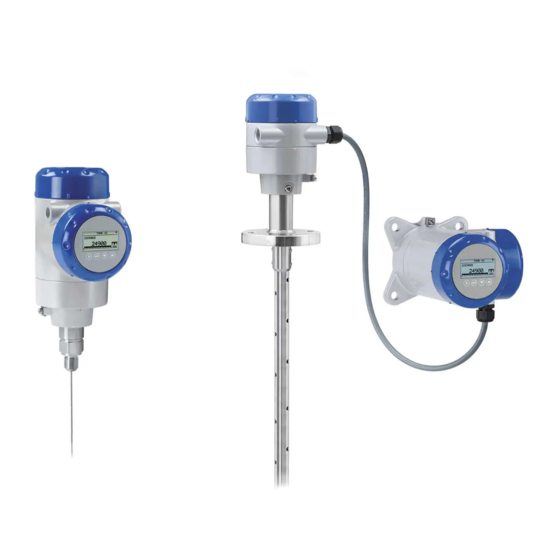
INSTALLATION DR2000 2.2 Scope of delivery INFORMATION! Do a check of the packing list to make sure that you have all the elements given in the order. Figure 2-1: Scope of delivery 1 Signal converter and probe. 2 Probe segments. For the assembly procedure of the single rod probe, refer to the instructions that are supplied with the device. -
Page 7: Visual Check
INSTALLATION DR2000 2.3 Visual check INFORMATION! Inspect the packaging carefully for damages or signs of rough handling. Report damage to the carrier and to the local office of the manufacturer. Figure 2-2: Visual check 1 Device nameplate (for more data, refer to the handbook) 2 Process connection data (size and pressure rating, material reference and heat number) 3 Gasket material data –... -
Page 8: Storage
INSTALLATION DR2000 2.4 Storage WARNING! Do not keep the device in a vertical position. This will damage the probe and the device will not measure correctly. Figure 2-4: Storage conditions 1 Do not bend rod and coaxial probes – support here 2 Storage temperature range: -50…+85°C / -60…+185°F (min. -
Page 9: Pre-Installation Requirements
INSTALLATION DR2000 2.6 Pre-installation requirements INFORMATION! Obey the precautions that follow to make sure that the device is correctly installed. • Make sure that there is sufficient space on all sides. • Protect the signal converter from direct sunlight. If necessary, install the weather protection accessory. - Page 10 INSTALLATION DR2000 Permitted temperature ranges for gaskets Gasket material Permitted temperature ranges for gaskets Standard version High-Temperature version [°C] [°F] [°C] [°F] FKM/FPM -40…+150 -40…+302 -40…+300 -40…+572 Kalrez® 6375 -20…+150 -4…+302 -20…+300 -4…+572 EPDM -50…+150 -58…+302 -50…+250 -58…+482 Compact version: Ambient temperature / flange temperature, flange and threaded connection, in °C...
- Page 11 INSTALLATION DR2000 INFORMATION! When the process temperature is -50 C / -58 F and the device has an EPDM gasket, there is a ° ° de-rating for the ambient temperature: Compact version Compact version Compact version Compact version = -36 C / -32.8...
-
Page 12: General Information For Nozzles
INSTALLATION DR2000 INFORMATION! When the process temperature is -50 C / -58 F and the device has an EPDM gasket, there is a ° ° de-rating for the ambient temperature: Remote version (probe housing) Remote version (probe housing) Remote version (probe housing) - Page 13 INSTALLATION DR2000 Figure 2-12: How to prevent build-up of product around the process connection 1 If product particles are likely to collect in holes, a nozzle is not recommended. 2 Attach the flange directly to the tank. 3 Use a threaded connection to attach the device directly to the tank.
-
Page 14: Installation Requirements For Concrete Roofs
INSTALLATION DR2000 For double cable and double rod probes: Figure 2-15: Recommended nozzle dimensions for double rod and double cable probes d ≥ 50 mm / 2¨, where d is the diameter of the tank nozzle For coaxial probes: If your device has a coaxial probe, you can ignore these installation recommendations. -
Page 15: Installation Recommendations For Liquids
INSTALLATION DR2000 2.8 Installation recommendations for liquids 2.8.1 General requirements Figure 2-17: Installation recommendations for liquids 1 The electromagnetic (EM) field generated by the device. It has a radius of R . Make sure that the EM field is clear of objects and product flow. -
Page 16: Installation In Standpipes (Stilling Wells And Bypass Chambers)
INSTALLATION DR2000 2.8.2 Installation in standpipes (stilling wells and bypass chambers) Use a standpipe if: • The liquid is very turbulent or agitated. • There are too many other objects in the tank. • The device is measuring a liquid in a tank with a floating roof. -
Page 17: Installation Recommendations For Solids
INSTALLATION DR2000 2.9 Installation recommendations for solids 2.9.1 Nozzles on conical silos We recommend that you prepare the installation when the silo is empty. DANGER! Risk of electrostatic discharge (ESD): The device is resistant to electrostatic discharges of up to 30 kV, but it is the responsibility of the fitter and the user to prevent ESD. -
Page 18: Traction Loads On The Probe
INSTALLATION DR2000 2.9.2 Traction loads on the probe Traction load depends on: • The height and shape of the tank. • The particle size and density. • The rate at which the tank is emptied. CAUTION! Risk of damage to the cable probe. High loads can break the cable. -
Page 19: How To Install The Device On The Tank
INSTALLATION DR2000 2.10 How to install the device on the tank 2.10.1 How to assemble the single rod probe (single-piece probe) INFORMATION! This procedure is for devices with single rod probes that are not segmented (single-piece probes). Figure 2-21: Equipment needed to assemble the device... - Page 20 INSTALLATION DR2000 Part 1: Check the order number on each component Figure 2-22: Part 1: Check the order number on each component • Make sure that the housing and the single rod have the same ID numbers. • Remove the sticker from the probe.
- Page 21 INSTALLATION DR2000 Part2: How to attach the locking nut and union nut Figure 2-23: Part2: How to attach the locking nut and union nut 1 Attach a locking nut to the housing assembly. 2 Make sure that the nut is fully engaged on the thread.
- Page 22 INSTALLATION DR2000 Part 3: How to attach the locking nut and union nut Figure 2-24: Part 3: How to attach the locking nut and union nut CAUTION! Support the probe. 1 Attach a locking nut to the single rod. 2 Make sure that the locking nut is engaged ¾ along the length of the thread.
-
Page 23: How To Assemble The Single Rod Probe (Segmented Probe)
INSTALLATION DR2000 2.10.2 How to assemble the single rod probe (segmented probe) INFORMATION! This procedure is for devices with single rod probes that are segmented. Figure 2-25: Equipment needed to assemble the single rod probe (segmented) 1 Converter and process connection... - Page 24 INSTALLATION DR2000 Part 1: How to assemble the segmented single rod probe Figure 2-26: Part 1: How to assemble the segmented single rod probe CAUTION! Make sure that the nuts are tight and the rod probe cannot loosen. 1 Attach a lock nut to the threaded rod below the process connection. Turn the nut until it is ¾...
- Page 25 INSTALLATION DR2000 Part 2: How to assemble the segmented single rod probe Figure 2-27: Part 2: How to assemble the segmented single rod probe WARNING! Put a support below the probe to prevent deformation. CAUTION! Make sure that the nuts are tight and the rod probe cannot loosen.
-
Page 26: How To Assemble The Segmented Coaxial Probe
INSTALLATION DR2000 2.10.3 How to assemble the segmented coaxial probe Figure 2-28: Equipment needed to assemble the coaxial probe 1 Converter and process connection 2 HC M4×20 screws (1 screw per probe segment) 3 Lock washers (1 pair of washers per probe segment) 4 Top (quantity: 1), middle (quantity: 1 or more) and bottom (quantity: 1 –... - Page 27 INSTALLATION DR2000 Part 1: How to assemble the segmented coaxial probe Figure 2-29: Part 1: How to assemble the segmented coaxial probe CAUTION! Do not attach the screw to the end of the rod segment that has a groove for the attachment of a PTFE spacer.
- Page 28 INSTALLATION DR2000 Part 2: How to assemble the segmented coaxial probe Figure 2-30: How to assemble the segmented coaxial probe: part 2 WARNING! Be careful when you use the pipe wrenches. Make sure that the measuring tubes have no deformation.
-
Page 29: How To Install A Device With A Flange Connection
INSTALLATION DR2000 Part 3: How to assemble the segmented coaxial probe Figure 2-31: Part 3: How to assemble the segmented coaxial probe CAUTION! If the lock screw is not tight, the device will not measure correctly. 1 Use a 2.5 mm Allen wrench to attach and tighten a HC M5×5 screw (lock screw) to the bottom segment of tube. -
Page 30: How To Install A Device With A Threaded Connection
INSTALLATION DR2000 2.10.5 How to install a device with a threaded connection Equipment needed: • Device • Gasket (not supplied) • 50 mm / 2¨ wrench (not supplied) Figure 2-33: Threaded connection • Make sure the tank connection is level. -
Page 31: How To Install A Device With A Hygienic Connection
INSTALLATION DR2000 2.10.6 How to install a device with a hygienic connection CAUTION! Make sure that you do not damage the polished parts. INFORMATION! To make the cleaning of the probe easier, attach the device to a short socket. Tri-Clamp®... -
Page 32: How To Install A Cable Probe In The Tank
INSTALLATION DR2000 Figure 2-35: DIN 11851 connection 1 Tank socket 2 Union nut for DIN 11851 connection • Make sure that the tank connection is level. • Make sure that you use the applicable gasket for the connection dimensions and the process. -
Page 33: How To Turn Or Remove The Signal Converter
INSTALLATION DR2000 Figure 2-37: Installation of devices with cable probes 1 >1 m / 3½ ft • Use two persons to lift the housing and the probe above the process connection. • Hold the device 1 m / 3½ ft above the tank. -
Page 34: Recommendations For Pits And Tanks Made Of Non-Conductive Materials
INSTALLATION DR2000 CAUTION! If you remove the housing, put a cover on the coaxial hole on top of the process connection assembly. When the housing is attached to the process connection assembly, tighten the lock screw with the 5 mm Allen wrench 1. -
Page 35: Wall Support For The Remote Version
INSTALLATION DR2000 2.10.10 Wall support for the remote version Figure 2-40: Wall support for the remote version (attached to the remote converter) 1 Use marks on the wall to help you put the wall support in the correct position. For more data, refer to "Dimensions and Weights"... - Page 36 INSTALLATION DR2000 Figure 2-42: Installation of the weather protection on a vertical signal converter INFORMATION! Install the weather protection after you connect the device to the power supply. 1 Put the weather protection clamp around the top of the device. Make sure that the locking nuts on the clamp are aligned with the cable entries.
- Page 37 INSTALLATION DR2000 Figure 2-43: Installation of the weather protection on a horizontal signal converter INFORMATION! Install the weather protection after you connect the device to the power supply. 1 Put the weather protection clamp around the front of the device (the end of the device that is nearest to the cable entry).
-
Page 38: How To Open The Weather Protection
INSTALLATION DR2000 The overall dimensions of the weather protection are in "Dimensions and weights" in the handbook. 2.10.12 How to open the weather protection Figure 2-44: How to open the weather protection INFORMATION! Electrical installation: Electrical installation: Electrical installation: Electrical installation: Remove the weather protection before you open the terminal compartment cover. -
Page 39: Electromagnetic Compatibility
INSTALLATION DR2000 2.11 Electromagnetic compatibility The device design agrees with the Electromagnetic Compatibility (EMC) Directive and the related European Standard when installed in metallic tanks. You can install the device on open-air tanks and tanks that are not made of metal. Refer also to the note that follows. -
Page 40: Electrical Connections
ELECTRICAL CONNECTIONS DR2000 3.1 Electrical installation: 2-wire, loop-powered 3.1.1 Compact version Terminals for electrical installation Figure 3-1: Terminals for electrical installation 1 Grounding terminal in the housing (if the electrical cable is shielded) 2 Current output - 3 Current output +... - Page 41 ELECTRICAL CONNECTIONS DR2000 3 Remove the cover. Figure 3-3: Procedure for electrical installation Equipment needed: • Small slotted tip screwdriver (not supplied) Procedure: 1 Do not disconnect the safety cord from the terminal compartment cover. Put the terminal compartment cover adjacent to the housing.
-
Page 42: Remote Version
ELECTRICAL CONNECTIONS DR2000 3.1.2 Remote version Terminals for electrical installation Figure 3-5: Terminals for electrical installation 1 Grounding terminal in the housing (if the electrical cable is shielded) 2 Current output - 3 Current output + 4 Location of the external grounding terminal (on the wall support) INFORMATION! Electrical power to the output terminal energizes the device. -
Page 43: Non-Ex Devices
ELECTRICAL CONNECTIONS DR2000 3.2 Non-Ex devices Figure 3-7: Electrical connections for non-Ex devices 1 Power supply 2 Resistor for HART® communication 3 Optional connection to the grounding terminal 4 Output: 11.5...30 V DC for an output of 22 mA at the terminal 5 Device 3.3 Devices for hazardous locations... -
Page 44: Minimum Power Supply Voltage
ELECTRICAL CONNECTIONS DR2000 3.4 Minimum power supply voltage Use these graphs to find the minimum power supply voltage for a given current output load. Non-Ex and Hazardous Location approved (Ex i / IS) devices Figure 3-8: Minimum power supply voltage for an output of 22 mA at the terminals (Non-Ex and Hazardous Location... -
Page 45: Protection Category
ELECTRICAL CONNECTIONS DR2000 3.5 Protection category INFORMATION! The device fulfils all requirements per protection category IP66 / IP67. It also fulfils all requirements per NEMA type 4X (housing) and type 6P (probe). DANGER! Make sure that the cable gland is watertight. -
Page 46: Networks
ELECTRICAL CONNECTIONS DR2000 3.6 Networks 3.6.1 General information The device uses the HART® communication protocol. This protocol agrees with the HART® Communication Foundation standard. The device can be connected point-to-point. It can also have a polling address of 1 to 63 in a multi-drop network. -
Page 47: Multi-Drop Networks
ELECTRICAL CONNECTIONS DR2000 3.6.3 Multi-drop networks Figure 3-12: Multi-drop network (non-Ex) 1 Address of the device (n+1 for multidrop networks) 2 Address of the device (1 for multidrop networks) 3 4 mA + HART® 4 Resistor for HART® communication 5 Power supply 6 HART®... -
Page 48: Fieldbus Networks
ELECTRICAL CONNECTIONS DR2000 3.6.4 Fieldbus networks For more data, refer to the supplementary instructions for PROFIBUS PA. PROFIBUS PA/DP network (non-Ex) Figure 3-13: PROFIBUS PA/DP network (non-Ex) 1 Field device 2 Bus termination 3 PROFIBUS PA bus segment 4 Segment coupler (PA/DP link) -
Page 49: Operation
OPERATION DR2000 4.1 General notes For more data about device configuration, refer to the handbook. 4.2 Digital display screen 4.2.1 Local display screen layout Figure 4-1: Local display screen layout in Normal mode 1 Current output percentage (bar graph and text — only shown if the current output function is the same as the mea-... -
Page 50: Commissioning
OPERATION DR2000 4.3 Commissioning Use this procedure to change the probe length and give the top and bottom measuring limits. Values and parameters that can be changed are shown between « ... » in the illustrations that follow. Push the keypad buttons in the correct sequence: CAUTION! Make sure that you do this procedure before you use the device. - Page 51 OPERATION DR2000 Screen Steps Description • [> > > > ] to change Scale 4 mA. Use this step to give the 4 mA output setting (0% limit) in the tank. Refer to the • [> > > > ] to change the position of the cursor.
-
Page 52: Probe Length Calculation
OPERATION DR2000 4.4 Probe length calculation CAUTION! • Make sure that you do this procedure before you use the device. If you decrease the probe length, do the probe length calculation procedure before the • snapshot procedure. The probe length cannot be less than 600 mm / 23.6 ¨... - Page 53 OPERATION DR2000 Procedure Screen Steps Description • [> > > > ], [ ] and [> > > > ]. Default screen. Enter configuration mode (2.0.0 SUPERVISOR). • [> > > > ], [^ ^ ^ ^ ], [ ], [ ], [> > > > ] and [^ ^ ^ ^ ].
-
Page 54: Snapshot
OPERATION DR2000 4.5 Snapshot The snapshot procedure is very important for the performance of the device. Make sure that the tank is empty or only filled to the minimum level before you do the procedure. Use this procedure (menu item 2.1.2) if there are objects adjacent to the probe that can cause parasitic signals. - Page 55 OPERATION DR2000 Procedure Screen Steps Description • [> > > > ], [ ] and [> > > > ]. Default screen. Enter configuration mode (2.0.0 SUPERVISOR). • [> > > > ], [^ ^ ^ ^ ], [ ], [ ], [> > > > ] and [^ ^ ^ ^ ].
- Page 56 AMETEK Drexelbrook makes no warranty of any kind with regard to the material contained in this manual, including, but not limited to, implied warranties or fitness for a particular purpose. Drexelbrook shall not be liable for errors contained herein or for incidental or consequential damages in connection with the performance or use of material.
Need help?
Do you have a question about the DR2000 and is the answer not in the manual?
Questions and answers