Table of Contents
Advertisement
Quick Links
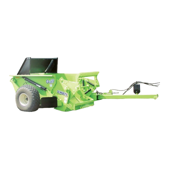
2500 GIANT
REEL TYPE ROCK PICKER
Effective S/N R 100003 28303 - R100000382308
Published 07/03
Part No. R100-03-1
73747 130TH ST
ZEARING IA 50276
641-487-7608
INFO@NESSAINC.COM
WWW.NESSAINC.COM
OPERATOR'S MANUAL
with PARTS LISTING
Schulte Industries Ltd.
P.O. Box 70
Englefeld Saskatchewan
Canada S0K 1N0
Tel. (306) 287-3715
Fax. (306) 287-3355
Parts Fax. (306) 287-4066
Email: info@schulte.ca
© 2003 Alamo Group Inc.
Advertisement
Table of Contents

Subscribe to Our Youtube Channel
Related Manuals for Alamo Schulte 2500 Giant


Summary of Contents for Alamo Schulte 2500 Giant
- Page 1 73747 130TH ST ZEARING IA 50276 641-487-7608 INFO@NESSAINC.COM WWW.NESSAINC.COM OPERATOR’S MANUAL with PARTS LISTING Schulte Industries Ltd. P.O. Box 70 Englefeld Saskatchewan Canada S0K 1N0 Tel. (306) 287-3715 Fax. (306) 287-3355 Parts Fax. (306) 287-4066 Email: info@schulte.ca © 2003 Alamo Group Inc.
- Page 2 To The Owner/Operator/Dealer This manual has been compiled to assist you in operating and servicing your new SCHULTE Rock Picker. READ and UNDERSTAND this manual BEFORE operating the Rock Picker. Pay special attention to the safety instructions. In addition to the design and configuration of equipment, hazard control and accident prevention are dependent upon the awareness, concern, prudence and proper training of personnel involved in the operation, transport, maintenance and storage of equipment.
-
Page 3: Table Of Contents
Parts Index ............5-20 Sch ulte 2500 Gian t July, 2003 SCHU LTE is a registered trademark of Alamo G roup Inc. -
Page 4: Dealer's Predelivery Service Guide
PREDELIVERY SERVICE IS REQUIRED BY DEALER OR END USER DEALER'S PREDELIVERY SERVICE GUIDE for SCHULTE ROCK PICKERS and ACCESSORIES DETAILS OF ITEMS LISTED BELOW ARE COVERED IN THIS OPERATOR'S MANUAL ____ Shipping damage corrected ____ Set up machine as outlined in the Assembly Instructions and Operator’s Manual. ____ Check that all safety decals are in good condition, replace if necessary. -
Page 5: Safety Section
SAFETY SECTION Sch ulte 2500 Gian t July, 2003... - Page 6 SAFETY SAFETY SAFETY A safe and careful operator is the best operator. Safety is of primary importance to the manufacturer and should be to the owner/operator. Most accidents can be avoided by being aware of your equipment, your surroundings, and observing certain precautions. The first section of this Manual includes a list of Safety Messages that, if followed, will help protect the operator and bystanders from injury or death.
- Page 7 SAFETY READ, UNDERSTAND, and FOLLOW the following Safety Messages. Serious injury or death may occur unless care is taken to follow the warnings and instructions stated in the Safety Messages. Always use good common sense to avoid hazards. (SG-2) PELIGRO! Si no lee Ingles, pida ayuda a alguien que si lo lea para que le tradu zca las m edidas d e se guridad.
- Page 8 SAFETY DANGER! Never allow children or other pers ons to ride o n the Tractor o r Imp lement. Falling off can res ult in serious injury or dea th. (SG-10) DANGER! Ne ver allow childre n to opera te or ride on the T ractor or Im plem ent. (SGM-11) WARNING! Do not mount th e T racto r while the Tractor is moving.
- Page 9 SAFETY WARNING! The ope rator and all support p ersonn el sho uld w ear h ard h ats, safety shoes, safety glasses, and proper he aring pro tec tion at all times for protection from injury including injury from items thrown by the E quipme nt. (SG-16) CAUTION! PROLONGED EXPOSURE TO LOUD NOISE MAY CAUSE PERMANENT...
- Page 10 SAFETY WARNING! Never attempt to lubricate, adjust, or remove material from the Implement while it is in motion or while Tractor engine is running. Make sure the Tractor engine is off before working on the Imp lement. (SG-20) WARNING! Pe riodically inspect all moving parts for wear and replace w hen nec essary with authorized se rvice parts .
- Page 11 SAFETY DANGER! NEVER use drugs or alcohol immediately before or while operating the Tractor and Implement. Drugs and alcohol will affect an operator's alertness and coordination and therefore affect the operator's ability to operate the Equipment safely. Before operating the Tractor or Implement, an operator on prescription or ov er-the-coun ter m edication m ust consult a medical professional reg arding any side effec ts o f the medication that would hinder the ir ability to operate the Equ ipment safely.
- Page 12 SAFETY DANGER! Th is Implement is wider than the T racto r. Be carefu l wh en operatin g or tra nsporting this Equipment to preven t the Im plem ent from runn ing into or striking sign posts, gua rd rails, concrete abu tme nts or other solid objects.
-
Page 13: Decals
SAFETY Decals Ref. Part No. Description Qty. 226-146 Decal "Warning Read Manual..." 226-144 Decal "Danger Moving Part..." 226-148 Decal "Warning High Pressure" 226-150 Decal "Warning Jammed Batt..." 226-151 Decal "Danger Thrown Rock..." 226-153 Decal Red Reflector 226-154 Decal Amber Reflector 226-013 Decal SMV Emblem 226-020... - Page 14 SAFETY Decal # 226-146 Decal # 226-151 Location : Hitch pole Location: Bucket, left and right side Decal # 226-144 Location: Right grate panel and left frame Decal # 226-148 Location : Hitch pole 1-10 Sch ulte 2500 Gian t July, 2003...
- Page 15 SAFETY Decal # 226-150 Decal # 226-193 Location: Right grate panel and left frame Location: Inside chain case Decal # 226-191 Location : Hitch pole 1-11 Sch ulte 2500 Gian t July, 2003...
- Page 16 1-12 Sch ulte 2500 Gian t July, 2003...
-
Page 17: Introduction Section
INTRODUCTION SECTION Sch ulte 2500 Gian t July, 2003... - Page 18 INTRODUCTION The 2500 Giant Rock Picker is a reel type rock picking implement designed primarily for picking surface rock 2" [51mm] to 27" [686mm] in diameter. With proper maintenance as described in this manual, your Rock Picker will provide you with years of dependable service with a minimum of repairs.
-
Page 19: General Data
INTRODUCTION General Data 2500 Giant Weight (approx.) 4970 lbs. (2254 kg) Overall length 205" (5.207 m) Overall width 114" (2.896 m) Height w/ rock deflector 81" (2.057 m) Hopper capacity 2.5 cubic yards (1.94 m Dumping height 49" (1.245 m) Tire size 16.5L x 16.1SL Power requirement... - Page 20 Sch ulte 2500 Gian t July, 2003...
-
Page 21: Operation Section
OPERATION SECTION Sch ulte 2500 Gian t July, 2003... -
Page 22: Preparation For Operation
OPERATION Preparation for Operation 1. Adjust the front hitch clevis up or down so that the rock picker main frame is parallel to the ground or as near as possible. Make sure that the tractor draw pin is retained on the bottom side, otherwise it may work loose during operation disconnecting the rock picker from the tractor. -
Page 23: Motor Valve Kit
OPERATION 7. Two transport pins are provided on the grate as a safety feature to be used while transporting the machine on public roads. A hairpin is provided for holding the transport pins in place. Refer to Figure 3-3. IMPORTANT: Remember to place the pin in the storage position before operating the hydraulic lift cylinders. - Page 24 OPERATION 1. Adjust the reel speed to 30-40 RPM. Refer Figure 3-2 in ‘Preparation for Operation’ section. Reel speed can be adjusted using the flow control valve on the rock picker. Adjust the lever on the flow control valve until proper reel speed is obtained then lock the lever in place using the screw on the valve.
-
Page 25: Transportation
OPERATION WARNING! SHUT DOWN the tractor completely before servicing or adjusting any part of the machine. Transportation CAUTION! Always install the transport pins before transporting the machine on public roads. 1. Swing the rock picker into transportation position using the following procedure. Refer to Figure 3-1 in ‘Preparation for Operation’. -
Page 26: Transport Light Kit
OPERATION Transport Light Kit Installation of Lights The light assemblies are installed onto the left and right rock deflector uprights. Drill 3/8" diameter holes as shown and install lights with 5/16" x 3/4" bolts and lock nuts. Install the lights with the red and amber lenses facing to the rear, with the amber on top. -
Page 27: Troubleshooting
OPERATION Troubleshooting Symptom Problem Correction Reel does not turn Oil not getting into hydraulic Check hydraulic connections motor Check tractor flow control valve Throwing rocks over back Reel speed too fast Adjust flow control on tractor Reel not sweeping rocks into Batt springs too loose Tighten springs bucket... - Page 28 Sch ulte 2500 Gian t July, 2003...
-
Page 29: Maintenance Section
MAINTENANCE SECTION Sch ulte 2500 Gian t July, 2003... -
Page 30: Drive Chain
MAINTENANCE NOTE: Experience has shown that the majority of breakdowns are the result of inadequate or improper service and inspection. Drive Chain Apply oil periodically with a brush or spout can, preferably at least once every 8 hours of operation and after use, this allows the oil to soak into the chain joints. -
Page 31: Hubs And Spindles
MAINTENANCE Hubs And Spindles Check hubs weekly for bearing play and condition of seal. Greasing and Installation It is recommended that hubs are dismantled, cleaned and repacked every year. Use the diagram and following instructions for maintaining the wheel hubs. Whenever a worn or damaged seal is replaced the bearing assembly should be cleaned and repacked with a good grade of wheel grease. -
Page 32: Tires
MAINTENANCE Tightening Instructions for 812 Hubs Proper setting for the tapered roller bearings is described in the following procedure. Always use a new cotter pin when making adjustments to the hubs. 1. Tighten the castle nut to 50 foot punds while turning hub clockwise. Then back the nut off 1/2 of a turn. -
Page 33: Batt Springs
MAINTENANCE Batt Springs Adjust the eyebolts on the batt springs so that the spring coils JUST begin to clear one another. Occasionally check and adjust the batt springs. IMPORTANT: Do not overtighten the batt springs as this will cause damage to the springs and reduce the cushioning effect when picking larger rocks. - Page 34 MAINTENANCE STORAGE If possible, store your rock picker under cover. Install hitch jack on lug at front of hitch pole. It is recommended that drive chains be removed from the machine, cleaned and stored in oil over the winter months. If this is not possible apply oil to all chains and sprockets. Fully retract the hydraulic cylinders and install the transport pins.
-
Page 35: Parts Section
PARTS SECTION Sch ulte 2500 Gian t July, 2003... -
Page 36: Main Frame & Bucket
Main Frame & Bucket Sch ulte 2500 Gian t July, 2003... - Page 37 Main Frame & Bucket Ref. Part No. Description Qty. R100-101 Main frame R100-110 Hitch pole R100-120 Bucket R100-130 Bucket bearing R100-125 Lift link Sn# R10090002701 to R10090077712 R100-127 Lift link Sn# R10090078808 to Current 231-020 Base hitch 228-012 Hose organizer R100-105 Grate lock -up pin R100-117...
-
Page 38: Reel And Grate
Reel and Grate Sch ulte 2500 Gian t July, 2003... - Page 39 Reel and Grate Ref. Part No. Description Qty. R100-155 Grate, 2" tooth spacing R100-175 Grate, 1-1/2" tooth spacing R100-160 Reel 60-49 Batt, 7 tooth 230-005 Reel pin 579-034 Batt tooth 352-101 Flan ge b earing 2" bore, c om plete 356-100 Bearing insert 2"...
-
Page 40: Hub And Axle Assembly
Hub and Axle Assembly Sch ulte 2500 Gian t July, 2003... - Page 41 Hub and Axle Assembly Ref. Part No. Description Qty. R100-140 Ax le plate assembly 207-005 Seal 207-001 Bearing, inner 207-002 Race, inner 273-006 Grease zerk, self tapping 205-001 Hub c/w outer races 204-004 Race, outer 207-003 Bearing, outer 207-006 Dust cap 206-011 Hub, c/w items #2-9 211-002...
-
Page 42: Hitch Jack, Side Wind 10" Crown (232-500)
Hitch Jack, Side Wind 10" Crown (232-500) Ref. Part No. Description Qty. 232-651 Gear cover 232-652 Bushing 232-653 Gear 232-654 Bolt, 1/4 x 3 UNC 232-655 Nut, 1/4 UNC 232-656 Pin, long 232-657 Handle 232-658 Flat w ash er, ½ x 1 1/2 232-659 Lock pin &... -
Page 43: Tow Clevis
Tow Clevis Ref. Part No. Description Qty. 231-019 Double tow clevis 250-110 Bolt, 3/4 x 5 UNC 270-001 Lock nut, 3/4" UNC 231-020 Perfect hitch Note: Turn the base hitch over, as shown, when using the tow clevis. Sch ulte 2500 Gian t July, 2003... -
Page 44: Rock Deflector Kit (73-00)
Rock Deflector Kit (73-00) Ref. Part No. Description Qty. 73-05 Up right, (left) 73-03 Flap Hanger 270-001 Lock nut, 3/4" UNC 250-007 Locknut,, 1/2" UNC 250-115 Bolt, 3/4 x 2 UNC 73-04 Up right, (righ t) 250-095 Bolt, 5/8 x 1-1/2 UNC 270-004 Lock nut, 5/8"... -
Page 45: Hydraulic Circuit
Hydraulic Circuit Ref. Part No. Description Qty. 111-126 Hose assembly 131", 3/8 SW 126-119 Tube assembly 70-1/2" 525-197 Tube shield 54" 270-017 Lock nut, 3/8 UNC 108-005 Male tee, 3/4-16 JIC 37 111-228 Hose assembly 45", 3/8 SW 111-142 Hose assembly 33", 3/8 SW 108-043 Elbow, 90 deg. -
Page 46: Hydraulic Drive Assembly
Hydraulic Drive Assembly 5-12 Sch ulte 2500 Gian t July, 2003... - Page 47 Hydraulic Drive Assembly Ref. Part No. Description Qty. 111-156 Hose assembly 105", JIC x NPT 111-242 Hose assembly 95", JIC x NPT 108-045 Elbow, 3/4-16 JIC x 7/8-14 ORB 108-031 Elbow, 3/4-16 JIC 108-005 Ma le Tee, 3/4-16 J IC 111-153 Ho se a sse mb ly 13", O RB x JIC 111-154...
-
Page 48: Hydraulic Motor, Char Lynn, 14.9 In (116-006)
Hydraulic Motor, Char Lynn, 14.9 in (116-006) 5-14 Sch ulte 2500 Gian t July, 2003... - Page 49 Hydraulic Motor, Char Lynn, 14.9 in (116-006) Ref. Part No. Description Qty. Seal, dust 117-960 Housing, bearing, 2 bolt Seal, 3" ID Ring, back-up Seal, sha ft 117-012 117-961 Sh aft & bearing kit Seal, shaft face 117-962 Plate, wear Seal, o-ring , 5/16"...
-
Page 50: Motor Valve Kit, Main Assembly (R100-200)
Motor Valve Kit, Main Assembly (R100-200) Ref. Part No. Description Qty. 111-245 Hose assembly, 28 ", 1/2" DW 270-017 Lock nut, 3/8" UNC 250-018 Bolt, 3/8" x 1" UNC 250-028 Bolt, 3/8" x 3-1/2" UNC 520-447 Va lve shield 108-030 Ru n tee, swivel, 3/4-16 J IC 108-025 Adapte r, 3/4-1 6 O RB x 3/4-16 J IC... - Page 51 Motor Valve Kit, Electrical Assembly Ref. Part No. Description Qty. 277-004 Wiring harness, solenoid, 12' 275-020 Terminal, 14-16 Ga., stud size 3/8" 277-003 Wiring harness, switch, 4' 277-007 Wiring harness, fused, split, batt. 4' 277-005 Replacement fuse, 5 AMP 275-002 Push switch 431-02 Mounting bracket, switch...
-
Page 52: Hydraulic Cylinder, 3 X 36 Tc Monarch (100-3271)
Hydraulic Cylinder, 3 x 36 TC Monarch (100-3271) Ref. Part No. Description Qty. 101-201 Clevis cap, TC 101-026 Seal kit 101-209 Cylinder tube, 3 x 36 257-022 Nut, 1/2" UNC 101-206 Rod clevis 101-207 Rod cap, TC 101-004 Piston 250-023 Clevis bolt, 3/8 x 1-3/4 UNC 257-032 Nut, 3/8"... -
Page 53: Transport Kits
Transport Kits Safety Chain (S000-010) 10,1 00 lbs . capacity, 59" m in. length NOTE: This safety chain is intended as an auxiliary atta ching syste m per ASA E S 338.3 . Th e safe ty c hain w ill help con trol the ro ck p icker sho uld it acc identally separa te from the draw bar. -
Page 54: Parts Index
Parts Index Part Number Page Part Number Page 100-3271 ......11, 18 207-005 ....... . . 7 101-004 . - Page 55 256-014 ....... . 13 73-04 ........10 256-017 .
- Page 56 SCHULTE INDUSTRIES LIMITED WARRANTY POLICY ON SCHULTE ROCK PICKERS Schulte Industries Limited ("the manufacturer") warrants to the original purchaser only, that in the event of any defect in material or workmanship in the Rock Picker, the subject of this warranty ("the goods") during the warranty period mentioned below the manufacturer will provide the cover specified below.
- Page 57 COVER In respect of claims notified: Commercial use - During the first six (6) months, parts and labour on repair. Non-commercial, governmental, municipal or farm use - During the first twelve (12) months, parts and labour on repair. Rental use - During the first thirty (30) days, parts and labour on repair. The buyer is responsible for any labour charges exceeding a reasonable amount as determined by the manufacturer and for returning the goods to the dealer, whether or not the claim is approved.
- Page 58 ©2003 Alamo Group Inc. Printed in Canada...
Need help?
Do you have a question about the Schulte 2500 Giant and is the answer not in the manual?
Questions and answers