Advertisement
Quick Links
INSTALLATION AND MAINTENANCE INSTRUCTIONS
FSP-951-SELFT
Intelligent Photoelectric
Self-Test Smoke Sensor
SPECIFICATIONS
Operating Voltage Range:
Operating Current @ 24 VDC:
Maximum Alarm Current:
Maximum Self-Test Alarm Current:
Maximum Current:
Operating Humidity Range:
Operating Temperature Range:
Storage Temperature Range:
Air Velocity:
Air Velocity using Self-Test:
Height:
Diameter:
Weight:
Isolator Load Rating:
*Please refer to your isolator base/module manual for isolator calculation instructions.
UL 268 listed for Open Air Protection.
This sensor must be installed in compliance with the control panel system
installation manual. The installation must meet the requirements of the Au-
thority Having Jurisdiction (AHJ). Sensors offer maximum performance when
installed in compliance with the National Fire Protection Association (NFPA);
see NFPA 72.
GENERAL DESCRIPTION
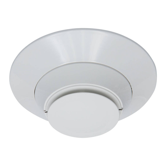
Model FSP-951-SELFT is a plug-in type smoke sensor that combines a photo-
electronic sensing chamber with addressable-analog communications.
The sensor transmits an analog representation of smoke density over a com-
munication line to a control panel. Rotary dial switches are provided for set-
ting the sensor's address. (See Figure 1.)
FIGURE 1. ROTARY ADDRESS SWITCHES
7
8
6
9
5
10
11
4
12
3
13
2
14
1 0
15
TENS
Two LEDs on the sensor are controlled by the panel to indicate sensor status.
An output is provided for connection to an optional remote LED annunciator
(P/N RA100Z).
Notifier panels offer different features sets across different models. As a result,
certain features of the photoelectric sensors may be available on some con-
trol panels, but not on others. FSP-951-SELFT will support only FlashScan®
protocol mode. The possible features available in the photoelectric sensors, if
supported by the control panel are:
1. The sensor's LEDs can operate in three ways—on, off, and blinking–and
they can be set to red, green, or amber. This is controlled by the panel.
2. The remote output may be synchronized to the LED operation or con-
trolled independent of the LEDs.
3. Devices are point addressable up to 159 addresses.
5. Yearly maintenance, in accordance to NFPA 72, can use the built in Self-
Test functionality.
Please refer to the operation manual for the UL listed control panel for specific
operation. The photoelectric sensors require compatible addressable com-
munications to function properly. Connect these sensors to listed-compatible
control panels only.
SPACING AND MOUNTING
Notifier recommends spacing sensors in compliance with NFPA 72. In low air
flow applications with smooth ceilings, space sensors 30 feet apart (9.1 m).
For specific information regarding sensor spacing, placement, and special ap-
plications, refer to NFPA 72 or the System Smoke Detector Application Guide,
available from Notifier. If using the self-test application, the FSP-951-SELFT
15 to 32 VDC
200 uA (one communication every 5 seconds with green LED blink on communication)
2 mA @ 24 VDC (one communication every 5 seconds with red LED solid on)
300 mA (Not be used for battery standby calculation as Self-Test will not work in auxiliary power mode)
4.5 mA @ 24 VDC (one communication every 5 seconds with amber LED solid on)
10% to 93% Relative Humidity, Non-condensing
32°F to 122°F (0°C to 50°C)
-4°F to 140°F (-20°C to 60°C)
0 to 4000 ft./min. (0 to 1219.2 m/min.)
0 to 300 ft./min. (0 to 304.8 m/min.)
2.0˝ (51 mm) installed in B300-6 Base
6.2˝ (156 mm) installed in B300-6 Base; 4.1˝ (104 mm) installed in B501 Base
3.5 oz. (100 g)
0.0063*
7
8
6
9
5
4
3
2
1 0
C0162-00
ONES
should be placed more than 3ft (914mm) away from any strong air source
which is greater than 300 ft./min. (e.g. an air conditioning outlet).
Duct Applications: FSP-951-SELFT is not listed for use in ducts.
Mounting Note: Units installed on ceilings must remain in ceiling-oriented
position; those mounted on walls must remain in the wall orientation.
WIRING GUIDE
All wiring must be installed in compliance with the National Electrical Code,
applicable local codes, and any special requirements of the Authority Having
Jurisdiction. Proper wire gauges should be used. The installation wires should
be color-coded to limit wiring mistakes and ease system troubleshooting. Im-
proper connections will prevent a system from responding properly in the
event of a fire. Please note that installation distances, wiring styles and wire
gauge requirements may vary for Self-Test sensors in comparison to standard
sensors, please refer to the panel's SLC Wiring documentation for further in-
formation.
Remove power from the communication line before installing sensors.
1. Wire the sensor base (supplied separately) as shown in the wiring
diagram. (See Figure 2.)
2. Set the desired address on the sensor address switches. (See Figure 1.)
3. Install the sensor into the sensor base. Push the sensor into the base while
turning it clockwise to secure it in place.
4. After all sensors have been installed, apply power to the control panel and
activate the communication line.
5. Test the sensor(s) as described in the TESTING section of this manual.
Dust covers provide limited protection against airborne dust particles during
shipping. Dust covers must be removed before the sensors can sense smoke.
Remove sensors prior to heavy remodeling or construction. The Self-Test func-
tion of your Notifier system can determine that all dust covers on the SLC
have been removed when you run the Self-Test process in order to prove that
there isn't anything causing a potential obstruction for smoke entry.
1
12 Clintonville Road
Northford, CT 06472-1653
Phone: 203.484.7161
CAUTION
I56-6782-000
1/6/2021
Advertisement

Related Manuals for Honeywell NOTIFIER FSP-951-SELFT


Summary of Contents for Honeywell NOTIFIER FSP-951-SELFT
- Page 1 INSTALLATION AND MAINTENANCE INSTRUCTIONS FSP-951-SELFT Intelligent Photoelectric 12 Clintonville Road Northford, CT 06472-1653 Self-Test Smoke Sensor Phone: 203.484.7161 SPECIFICATIONS Operating Voltage Range: 15 to 32 VDC Operating Current @ 24 VDC: 200 uA (one communication every 5 seconds with green LED blink on communication) Maximum Alarm Current: 2 mA @ 24 VDC (one communication every 5 seconds with red LED solid on) Maximum Self-Test Alarm Current:...
- Page 2 This sensor contains a wireless beacon (only active during Self-Test process) 2. Remove the sensor cover by pressing firmly on each of the four removal which is designed to communicate with the Honeywell Connected Life Safety tabs that hold the cover in place. (See Figure 4.) Services app in order to prove the successful completion of the visual inspec- 3.
- Page 3 FIGURE 3. FEATURES OF THE PHOTO DETECTOR Magnet Test Base Alignment Notch Marker Base Alignment Notch Magnet Test Marker C2021-00 FIGURE 4. CLEANING THE PHOTO DETECTOR Sensor Cover Sensing Chamber Cover Cover and Screen Removal Sensing Chamber Tabs C2022-00 SPECIAL APPLICATION When configured at the fire alarm control panel, this detector is capable of op- erating in a special application mode such that it has a higher sensitivity than is normally allowed by UL 268 for areas where early warning is important.
- Page 4 Limitations of Fire Alarm Systems Notifier ® and FlashScan ® are registered trademarks of Honeywell International, Inc. I56-6782-000 ©2021 Notifier. 1/6/2021...
Need help?
Do you have a question about the NOTIFIER FSP-951-SELFT and is the answer not in the manual?
Questions and answers