
Related Manuals for UFM UFM-40 Series


Summary of Contents for UFM UFM-40 Series
- Page 3 UFM-40 Ultrasonic transit-time flowmeter Product Components Inspection should be made before installing the Flowmeter. Check to see if the spare parts are in accordance with the packing list. Make sure that there is no damage to the enclosure due to a loose screw or loose wire, or other damage that may have occurred during transportation.
- Page 4 UFM-40 Ultrasonic transit-time flowmeter Content 1. Transmitter Installation and Connection ..................... 6 1.1. Inspection Prior to Transmitter Installation ....................6 1.2. Wire Connecting ............................... 7 1.2.1 Power Supply Option ..........................7 1.2.2 Transmitter Wiring ............................. 7 1.2.3 Lengthened Cable Method ........................
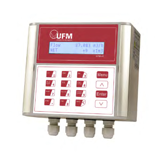
- Page 9 UFM-40 Ultrasonic transit-time flowmeter The system will default to the last window settings and automatically display them at next power on. 1.4. Keypad Functions This keypad is dual function keypad: 1. When separately pressed, is shortcut function, referring to "2. Quickly set menu instructions ";...
- Page 14 UFM-40 Ultrasonic transit-time flowmeter 3. Measurement Site Selection When selecting a measurement site, it is important to select an area where the fluid flow profile is fully developed to guarantee a highly accurate measurement. Use the following guidelines to select a proper installation site: Choose a section of pipe that is always full of liquid, such as a vertical pipe with flow in the upward direction or a full horizontal pipe.
- Page 22 UFM-40 Ultrasonic transit-time flowmeter 6. Windows Display Explanations 6.1 Windows Display Codes Totalizer Multiplier Beeper Setup Flow Totalizer Display Flow Rate Net Total POS Totalizer OCT Output Setup Flow Rate/Velocity NEG Totalizer Relay Output Setup Date Totalizer Flow Rate/POS Totalizer...
- Page 23 UFM-40 Ultrasonic transit-time flowmeter 6.2 Display Explanation Flow 0.1154 m3/h *R Display Flow Rate Net Total Display Flow Rate and Velocity. Flow 0.1129 m3/h *R Flow Rate /POS Totalizer Display Flow Rate and POS Totalizer. Select the POS Totalizer units in Window M31.
- Page 24 UFM-40 Ultrasonic transit-time flowmeter Tn-Out-Delta C System Error Codes Display the Working Condition and the System Error 0.00 0.00 0.00 Codes. More than one error code can occur at the same time. The explanations of error codes and detailed resolution methods can be found in "Error Diagnoses".
- Page 26 UFM-40 Ultrasonic transit-time flowmeter Holding with Poor Sig Holding with PoorSig Select "Yes" to hold last good flow signal displayed if the Flowmeter experiences a poor signal condition. This function will allow to calculate flow totalizer data without interruption. Select "NO", instead.
- Page 27 UFM-40 Ultrasonic transit-time flowmeter Totalizer Units 0.Cubic Meters(m3) Totalizer Units Options Select totalizer units. The available unit options are as same as those found in Window M31. The user can select units as their requirement. Factory default is Cubic Meters.
- Page 30 UFM-40 Ultrasonic transit-time flowmeter CL mode Select 4-20mA Current Loop Mode Select 4-20mA set up the 4-20mA output to. be flow rate mode 0-20mA set up output range to be 0-20mA mode 4-20mA vs.Vel. set up the 4-20mA output to. be velocity mode 4-20mA vs.Energy...
- Page 31 UFM-40 Ultrasonic transit-time flowmeter CL Checkup leaving the factory. Press to start, press Press When Ready to display 0mA, 4mA, 8mA, 12mA, 16mA, 20mA, and at the same time, check with an ammeter to measure the current loop output current and calculate the differences to see if it is under the permitted tolerance.
- Page 33 UFM-40 Ultrasonic transit-time flowmeter Beeper Setup BEEPER Setup Set up the beeper on-off state. Beeper ON OFF Beeper OFF OCT Output Setup OCT Output Setup [78 Set OCT output hardware unit output trigger sources, 5. FO selection of triggering events:...
- Page 34 UFM-40 Ultrasonic transit-time flowmeter Automatic Flow Correction With the function of automatic flow correction, the flow lost in an offline session can be estimated and automatically adjusted. The estimate is based on the average value, which is obtained from flow rate before...
- Page 41 UFM-40 Ultrasonic transit-time flowmeter A data character string is used to express basic commands and a carriage return (ENTER) is used to express the end of a command. The characteristic is that the string of data is flexible. Frequently used commands are as...
- Page 42 UFM-40 Ultrasonic transit-time flowmeter If there are multiple flowmeters in a data network then the basic commands cannot be used alone. The prefix W must be added. Otherwise, multiple flowmeters will answer simultaneously, which will cause chaos in the system.
- Page 43 UFM-40 Ultrasonic transit-time flowmeter 9.3.2.2 MODBUS Protocol Function Code 0x03 Usage The host sends out the read register information frame format: Slave Address Operation First Address Register Register Number Verify Code Function Code 1 byte 1 byte 2 bytes 2 bytes...
- Page 44 UFM-40 Ultrasonic transit-time flowmeter Register Read Write Type No. registers* Address Flow/s - low word $0000 40001 32 bits real Flow/s - high word $0001 40002 Flow/m - low word $0002 40003 32 bits real Flow/m- high word $0003 40004...
- Page 45 UFM-40 Ultrasonic transit-time flowmeter 10. Appendix2-W210 Insertion Transducer 10.1 Overview W210 type insertion transducers can be installed into metal pipelines via an isolation ball valve (installation into pipelines of plastic or other materials may require an optional mounting seat). The maximum pipe diameter in which insertion transducers can be installed is DN2000.
- Page 48 UFM-40 Ultrasonic transit-time flowmeter key to select Pipe Material, and press the key to confirm. Step4. Transducers type Transducer Type [23 Press the keys to enter 1.Plug-in Type B45 the window M23, press the key to select transducer type, and press the key to confirm.
- Page 51 UFM-40 Ultrasonic transit-time flowmeter temperature for 100.Press key to enter inlet water temperature 100°C adjustment, press to adjust temperature for 100,press key to Complete calibration. Power on for many times,0°C:inlet and return water temperature is 0.00±0.05,Temperature difference is 0.00±0.05. 100°C:inlet and return water temperature is 100±0.05,Temperature difference is 0.00±0.05.
Need help?
Do you have a question about the UFM-40 Series and is the answer not in the manual?
Questions and answers