Table of Contents
Advertisement
Quick Links
Advertisement
Table of Contents

Related Manuals for VIA Technologies VAB-600


Summary of Contents for VIA Technologies VAB-600
- Page 1 USER MANUAL VAB-600 Pico-ITX Cortex-A9 Board 1.04-12192014-172500...
- Page 2 The information and product specifications within this document are subject to change at any time, without notice and without obligation to notify any person of such change. VIA Technologies, Inc. reserves the right the make changes to the products described in this manual at any time without prior notice.
- Page 3 Battery Recycling and Disposal Only use the appropriate battery specified for this product. Do not re-use, recharge, or reheat an old battery. Do not attempt to force open the battery. Do not discard used batteries with regular trash. Discard used batteries according to local regulations. Safety Precautions Always read the safety instructions carefully.
- Page 4 User Manual User Manual User Manual Box Contents VAB- - - - 600 1 x VAB-600 embedded board (with WM8950 Cortex-A9 processor) 1 x DC-In cable 1 x Front Panel cable 1 x Front Audio cable 1 x COM connector cable...
-
Page 5: Table Of Contents
VAB- - - - 600 600 User Manual User Manual User Manual User Manual Table of Contents 1. 1. 1. 1. Product Overview Product Overview ........ Product Overview Product Overview ........................................................................ 1 1 1 1 1.1. - Page 6 Appendix A. Mating Pin Header and Connector Vendor Lists ctor Vendor Lists ............37 Appendix A. Mating Pin Header and Conne Appendix A. Mating Pin Header and Conne ctor Vendor Lists ctor Vendor Lists ............37 37 A.1. VAB-600 Mainboard ..................37...
- Page 7 User Manual Lists of Figures Figure 1: Layout diagram of VAB-600 mainboard (top and bottom view) ..5 Figure 2: Mounting holes and dimensions of the VAB-600........7 Figure 3: Height distribution of VAB-600 mainboard (top and bottom side)..8 Figure 4: External rear I/O ports ..................
- Page 8 User Manual User Manual Lists of Tables Table 1: Layout diagram description table of VAB-600 mainboard...... 6 Table 2: Layout diagram description table of external rear I/O ports....9 Table 3: DC-In jack specifications ................10 Table 4: Micro SD Card slot pinout................11 Table 5: Mini USB 2.0 port pinout................
-
Page 9: Product Overview Product Overview
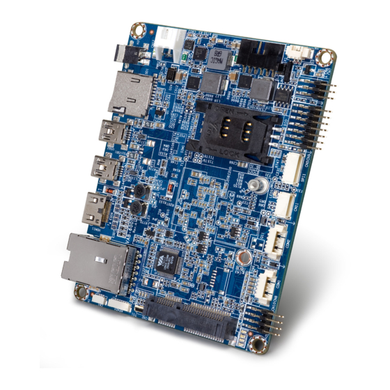
Product Overview Product Overview Product Overview VIA VAB-600 is an ultra compact Pico-ITX and highly integrated ARM based board measuring 10 cm x 7.2 cm. Powered by 800MHz WM8950 Cortex-A9 single-core processor, with built-in 3D/2D graphics engine and video multi- standard decoder. - Page 10 VAB- - - - 600 600 User Manual User Manual User Manual User Manual Support SIM card slot for 3G SIM card (used for 3G module without built-in SIM card slot) Support Micro SD Card slot for expandable storage Support RJ-45 LAN (Fast Ethernet), Mini HDMI and Mini USB 2.0 ports...
-
Page 11: Product Specifications
VAB- - - - 600 600 User Manual User Manual User Manual User Manual 1.2. Product Specifications Processor Processor Processor Processor WonderMedia (WM8950) Cortex-A9 Single-Core 800MHz System Memory System Memory System Memory System Memory Onboard 1GB DDR3 SDRAM 1066 ... - Page 12 VAB- - - - 600 600 User Manual User Manual User Manual User Manual 1 x 4-Wire Resistive Touch Screen connector (through VT1603A) 1 x GPIO and I²C pin header (for one I²C pair and eight GPIOs) 1 x +12V ~ +24V DC-In onboard connector ...
-
Page 13: Layout Diagram
VAB- - - - 600 600 User Manual User Manual User Manual User Manual 1.3. Layout Diagram Figure Figure 1 1 1 1 : Layout diagram of VAB : Layout diagram of VAB- - - - 600 mainboard (top and bottom view) 600 mainboard (top and bottom view) Figure Figure... - Page 14 VAB- - - - 600 600 User Manual User Manual User Manual User Manual Item Item Item Item Description Description Description Description PWR2: DC-In connector SIM1: SIM card slot (used for 3G module without built-in SIM card slot) CN3: Battery Charger connector (optional) BAT1: RTC Battery connector JM3: Power On Select jumper CN7: Front Panel pin header...
-
Page 15: Product Dimensions
VAB- - - - 600 600 User Manual User Manual User Manual User Manual 1.4. Product Dimensions Figure Figure Figure Figure 2 2 2 2 : Mounting holes and dimensions of the VAB : Mounting holes and dimensions of the VAB : Mounting holes and dimensions of the VAB : Mounting holes and dimensions of the VAB- - - - 600... -
Page 16: Height Distribution
VAB- - - - 600 600 User Manual User Manual User Manual User Manual 1.5. Height Distribution Figure Figure 3 3 3 3 : Height distribution of VAB : Height distribution of VAB- - - - 600 mainboard (top and bottom 600 mainboard (top and bottom side) side) Figure... -
Page 17: I/O Interface
2. 2. 2. 2. I/O Interface I/O Interface I/O Interface I/O Interface The VIA VAB-600 has a wide selection of interfaces integrated into the board. It includes a selection of frequently used ports as part of the external I/O coastline. 2.1. External I/O Ports... -
Page 18: Dc-In Jack
VAB- - - - 600 600 User Manual User Manual User Manual User Manual 2.1.1. DC-In Jack The mainboard comes with a coaxial power connector on the real I/O panel adjacent to the Micro SD slot. The power connector carriers +12V ~ +24V external power input. -
Page 19: Micro Sd Card Slot
VAB- - - - 600 600 User Manual User Manual User Manual User Manual 2.2. Micro SD Card Slot The Micro SD card slot is located on the rear I/O panel, it offers expandable storage. Figure Figure 6 6 6 6 : Micro SD Card : Micro SD Card slot diagram slot diagram Figure... -
Page 20: Mini Usb 2.0 Port
VAB- - - - 600 600 User Manual User Manual User Manual User Manual 2.2.1. Mini USB 2.0 Port There are two integrated Mini USB 2.0 ports located on the rear I/O panel. The Mini USB 2.0 interface port gives complete Plug and Play and hot swap capabilities for external devices and it complies with USB UHCI, rev. -
Page 21: Mini Hdmi ® Port
VAB- - - - 600 600 User Manual User Manual User Manual User Manual ® 2.2.2. Mini HDMI Port The integrated 19-pin Mini HDMI port uses an HDMI Type C receptacle ® connector as defined in the HDMI specification. The Mini HDMI port is for ®... -
Page 22: Lan Port (Fast Ethernet)
VAB- - - - 600 600 User Manual User Manual User Manual User Manual 2.2.3. RJ-45 LAN port (Fast Ethernet) The integrated 8-pin Fast Ethernet port is using an 8 Position 8 Contact (8P8C) receptacle connector (commonly referred to as RJ-45). The Fast Ethernet ports are controlled by VIA VT6113 10/100 Base-TX PHY chip controller. -
Page 23: Onboard Connectors
VAB- - - - 600 600 User Manual User Manual User Manual User Manual 2.3. Onboard Connectors 2.3.1. DC-In Connector The mainboard has an onboard DC-In 2-pin power connector to connect the DC-In power cable. The DC-In power connector is an optional power connector in addition to the DC-In jack on the rear IO panel. -
Page 24: Sim Card Slot
The mainboard is equipped with a SIM card slot located on the top side of the board which can support a 3G SIM card. Using the SIM card slot on VAB-600 requires a 3G module installed in the Mini Card expansion slot to enable the 3G function, otherwise the SIM card slot is disabled. -
Page 25: Battery Charger Connector (Optional)
VAB- - - - 600 600 User Manual User Manual User Manual User Manual 2.3.3. Battery Charger Connector (Optional) The mainboard is equipped with an onboard battery charger connector used for connecting the external cable for charging a rechargeable battery. The battery charger connector is labeled as “CN3”. -
Page 26: Rtc Battery Connector
VAB- - - - 600 600 User Manual User Manual User Manual User Manual 2.3.4. RTC Battery Connector The mainboard is equipped with an onboard RTC battery connector used for connecting the external cable battery that provides power to the 32.768KHz crystal oscillator for Real Time Clock (RTC). -
Page 27: Front Panel Pin Header
VAB- - - - 600 600 User Manual User Manual User Manual User Manual 2.3.5. Front Panel Pin Header The front panel pin header block consists of 6 pins. It provides access to the system power LED, power switch and shut down switch. The front panel pin header is labeled as “CN7”. -
Page 28: Gpio And I 2 C Pin Header
VAB- - - - 600 600 User Manual User Manual User Manual User Manual 2.3.6. GPIO and I C Pin Header The GPIO and I²C combination pin header block labeled as “CN9” is used for connecting the I²C device, and eight General Purpose Input and Output. The pinout of the combination pin header is shown below. -
Page 29: Spi Flash Connector
VAB- - - - 600 600 User Manual User Manual User Manual User Manual 2.3.7. SPI Flash Connector The mainboard has one 8-pin SPI flash connector. By connecting to the SPI BIOS programming fixture, the SPI (Serial Peripheral Interface) flash connector can update the SPI flash ROM. -
Page 30: Usb Connector
VAB- - - - 600 600 User Manual User Manual User Manual User Manual 2.3.8. USB Connector The mainboard includes one onboard USB connector designed for connecting the wireless LAN USB module. The connector is labeled as “CN11”. The pinout of the connector is shown below. Figure Figure 17 17: USB connector diagram... -
Page 31: Com Connector
VAB- - - - 600 600 User Manual User Manual User Manual User Manual 2.3.9. COM Connector There are two onboard COM connectors on the top side of the mainboard. The COM connectors labeled as “COM1” and ”COM2” are used to attach additional COM port that supports Tx/Rx. -
Page 32: Front Audio Pin Header
VAB- - - - 600 600 User Manual User Manual User Manual User Manual 2.3.10. Front Audio Pin Header The mainboard has a front audio pin header for connecting the Line-Out and Mic-In jacks. The pin header is labeled as “CN8”. The pinout of the pin header is shown below. -
Page 33: Mini Card Slot
2.3.11. Mini Card Slot The VAB-600 mainboard is equipped with a Mini card expansion slot labeled as “CN2”. The Mini card slot is used to attach the USB connectivity 3G module to provide 3G function. The pinout of the slot is shown below. - Page 34 VAB- - - - 600 600 User Manual User Manual User Manual User Manual VSUS33 LED_WWAN1- LED_WLAN1- LED_WPAN1- +1.5V VSUS33 Table Table Table Table 19 19 19 19: Mini Card slot pinout : Mini Card slot pinout : Mini Card slot pinout : Mini Card slot pinout...
-
Page 35: 4-Wire Resistive Touch Screen Connector
VAB- - - - 600 600 User Manual User Manual User Manual User Manual 2.3.12. 4-Wire Resistive Touch Screen Connector The mainboard is equipped with a touch screen connector for connecting the 4-wire resistive touch panel. The touch screen connector is labeled as “TS1”. The pinout of the connector is shown below. -
Page 36: Key Pad Connector
VAB- - - - 600 600 User Manual User Manual User Manual User Manual 2.3.13. Key PAD Connector The mainboard is equipped with a Key PAD connector for connecting the keypad device. The connector is labeled as “KPAD1”. The pinout of the connector is shown below. -
Page 37: Cir Connector
VAB- - - - 600 600 User Manual User Manual User Manual User Manual 2.3.14. CIR Connector The mainboard provides a CIR (Consumer Infrared Receiver) connector on the top side of the board. The CIR connector is used to connect the infrared receiver module to enable infrared wireless interface. -
Page 38: Dvo Connector
VAB- - - - 600 600 User Manual User Manual User Manual User Manual 2.3.15. DVO Connector The DVO (Digital Video Output) connector works as an interface for multi- display devices. This connector allows the mainboad to connect an additional daughter card which is required for a certain display such as TTL or LVDS display. - Page 39 VAB- - - - 600 600 User Manual User Manual User Manual User Manual LD08 I2C0SCL LD09 I2C0SDA LD10 DVO_CLK LD11 DVO_DATA LD12 LVDSENBL LD13 LVDSENVDD LD14 Table Table Table Table 23 23 23 23: DVO connector pinout : DVO connector pinout : DVO connector pinout : DVO connector pinout Caution:...
-
Page 40: Jumper
VAB- - - - 600 600 User Manual User Manual User Manual User Manual 3. 3. 3. 3. Jumper Jumper Jumper Jumper 3.1. Power On Select Jumper The Power On Select jumper is used to enable or disable the auto power On function when plug-in the power adaptor. -
Page 41: Hardware Installation Hardware Installation
VAB- - - - 600 600 User Manual User Manual User Manual User Manual 4. 4. 4. 4. Hardware Installation Hardware Installation Hardware Installation Hardware Installation 4.1. Installing 3G Module on Mini Card Slot Step 1 Step 1 Step 1 Step 1 Align the notch of 3G module with the notch on Mini Card slot. -
Page 42: Inserting 3G Sim Card On Sim Card Slot
VAB- - - - 600 600 User Manual User Manual User Manual User Manual 4.2. Inserting 3G SIM Card on SIM Card Slot The onboard SIM card slot is automatically enabled when the 3G module (without built-in SIM card slot) has been installed in the Mini Card expansion slot. - Page 43 VAB- - - - 600 600 User Manual User Manual User Manual User Manual Figure Figure 29 29: Locking the 3G SIM card slot : Locking the 3G SIM card slot Figure Figure 29 29 : Locking the 3G SIM card slot : Locking the 3G SIM card slot...
-
Page 44: Driver Installation
The latest drivers can be downloaded from the VIA Embedded website at www.viaembedded.com. 5.2. Linux Driver Support The VIA VAB-600 mainboard is highly compatible with Linux Kernel 3.0.8. Support and drivers are provided through various methods including: Drivers provided by VIA Using a driver built into a distribution package Visiting www.viaembedded.com for the latest updated drivers... -
Page 45: Ctor Vendor Lists
Mating Pin Header and Connector Vendor Lists and Connector Vendor Lists and Connector Vendor Lists and Connector Vendor Lists The following tables listed the mating pin headers and connectors vendor lists. A.1. VAB-600 Mainboard Label Label Function Function Pins Pins...
Need help?
Do you have a question about the VAB-600 and is the answer not in the manual?
Questions and answers