Table of Contents
Advertisement
Quick Links
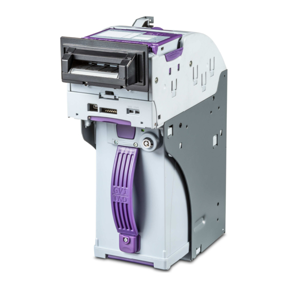
GBA Global Bill Acceptors
GBA GV1 Operation Manual
GVI
Operation Manual
This document is the copyright of Astrosys International Ltd. and may not be reproduced in total or in part by
any means, electronic or otherwise, without the prior written consent of Astrosys International Ltd.
Astrosys International Ltd
October 2018
GBA GV1 Operation Manual v2.00
Page 1 of 33
Advertisement
Table of Contents

Related Manuals for GBA GV1


Summary of Contents for GBA GV1
- Page 1 This document is the copyright of Astrosys International Ltd. and may not be reproduced in total or in part by any means, electronic or otherwise, without the prior written consent of Astrosys International Ltd. Astrosys International Ltd October 2018 GBA GV1 Operation Manual v2.00 Page 1 of 33...
-
Page 2: Table Of Contents
6.1 Programming ........................17 6.2 Programming Ports & Switches ................... 18 6.3 On-board Controls ....................... 19 6.3.1 GV1 DIP switches ......................19 7.0 ELECTRICAL INTERFACE SPECIFICATION ................. 20 7.1 Power ..........................20 7.1.1 Power Supply - absolute limits ..................20 7.2 Signal Interface ........................ -
Page 3: Introduction
GBA GV1 Operation Manual 1.0 INTRODUCTION This manual describes the operation and maintenance of the GBA GV1 integrated bill validator and stacker. It is intended to assist the user in the set-up, installation and operation of the product. If, after reviewing this manual, you have any questions about this or any other Astrosys products then please visit our web sites at www.globalbillacceptors.com... -
Page 4: Product Information
Units are typically completed by the addition of a (4) Noteguide Base with currency-specific noteguide inserts, and in some applications, the further addition of a (5) Bezel (varying designs). The GV1 unit allows rapid access to the major modules and their component elements, as shown in the following sections. -
Page 5: Removing The Head Unit Assembly
(or coupon etc) with optical sensing technology utilising Neural Network processing. As a plug-in module of GV1, the ST2 provides a number of significant advantages. The top-half of the ST2 module can be rotated or removed altogether for rapid access to the notepath surface, in conjunction with the hinged Roller Housing assembly of the GV1. - Page 6 ST2 top rotates back… Squeeze ST2 top-release or can be removed levers The above sequence can also be performed with the ST2 module in-place in the GV1 unit Astrosys International Ltd October 2018 GBA GV1 Operation Manual v2.00 Page 6 of 33...
-
Page 7: Removing The Cashbox
GBA Global Bill Acceptors GBA GV1 Operation Manual 2.2.3 Removing the Cashbox (2) Press Cashbox (1) Unlock Release Cashbox Button Astrosys International Ltd October 2018 GBA GV1 Operation Manual v2.00 Page 7 of 33... - Page 8 GBA Global Bill Acceptors GBA GV1 Operation Manual (3) Remove Cashbox Astrosys International Ltd October 2018 GBA GV1 Operation Manual v2.00 Page 8 of 33...
-
Page 9: Model Number Chart
2. 20-pin RS-232 (GBA) 3. MDB 'Y' 4. ccTalk® Accessories Other: 0. None 1. Square Base 2. 19mm Security Lock Assy 3. Security Switch & Loom not fitted Astrosys International Ltd October 2018 GBA GV1 Operation Manual v2.00 Page 9 of 33... -
Page 10: Note Entry Options
GBA Global Bill Acceptors GBA GV1 Operation Manual 3.0 NOTE ENTRY OPTIONS 3.1 Note Entries GV1 can be fitted with two key styles of Noteguide Entry: • Universal Note Guide - typically for gaming applications • Elite Gaming Bezel Entry... -
Page 11: Noteguide Inserts
GBA GV1 Operation Manual 3.2 Noteguide Inserts The GV1 unit must be configured with specific Outer & Inner Noteguide Inserts to handle the currency requirement at hand. These Inserts are generally fitted to suit customer requirements at the time of GV1 manufacture, but this section provides information should it be necessary to reconfigure the Note Entry area. -
Page 12: Fitting Outer Noteguides
GBA GV1 Operation Manual 3.2.2 Fitting Outer Noteguides The following sequence looks at taking a GV1 unit and disassembling the Note Entry area, for example, if the area needed to be reconfigured. Reassembly is essentially the reverse process, substituting different parts as required to achieve the desired arrangement. - Page 13 GBA Global Bill Acceptors GBA GV1 Operation Manual Slide Clamp moulding (2) back & out. Unplug PCB loom (3), lift Noteguide Base (4) out Astrosys International Ltd October 2018 GBA GV1 Operation Manual v2.00 Page 13 of 33...
-
Page 14: Cashbox
Audit facility - if specified, an Audit PCB is installed inside the Cashbox cap • Security Lock - for locking the Cashbox to the GV1 unit. 12mm Lock fitted as default or Cashbox configured to accept customer-supplied 19mm Lock •... - Page 15 GBA Global Bill Acceptors GBA GV1 Operation Manual The following illustration shows the Cashbox Lock options GV1 Locking Plate (ASY-M-720439) Astrosys International Ltd October 2018 GBA GV1 Operation Manual v2.00 Page 15 of 33...
-
Page 16: Mechanical Installation
GBA GV1 Operation Manual 5.0 MECHANICAL INSTALLATION The GV1 unit should be mounted in an upright and vertical manner, i.e. with the ST2 validation module at the top of the unit. Please contact your Astrosys office for advice on any variation to this arrangement. -
Page 17: Programming Gv1
USB device. It is worthwhile to understand that the overall functionality of GV1 is split between the ST2 validation module and the GV1 unit itself. The ST2 validation module is primarily concerned with the currency settings &... -
Page 18: Programming Ports & Switches
GBA Global Bill Acceptors GBA GV1 Operation Manual 6.2 Programming Ports & Switches The use of the ports & switches is explained in the comprehensive GV1 Reference Manual 'ST2' PUSHBUTTON 'ST2' DIAGNOSTIC LED 'ST2' USB PROGRAMMING PORT INTERFACE CONNECTOR(S) 'GV1' USB... -
Page 19: On-Board Controls
6.3.1 GV1 DIP switches An 8-way DIP switch block is located in the front door area of the GV1 Head Unit assembly. The switches can be accessed through the aperture in the door or the door can be swung-down for improved access. -
Page 20: Electrical Interface Specification
Current, Peak: Note: if at any time during operation, the voltage falls below 10.8V, note acceptance and operation speed may be significantly impaired. Low voltage at power-up will also inhibit the GV1 unit from completing its self-checking sequence. 7.2 Signal Interface 7.2.1 General Purpose... -
Page 21: Connection Options
GBA Global Bill Acceptors GBA GV1 Operation Manual 8.0 CONNECTION OPTIONS 20-pin Gaming 20-pin Illustration showing the Interface Connector options at the rear of the GV1 head assembly Astrosys International Ltd October 2018 GBA GV1 Operation Manual v2.00 Page 21 of 33... -
Page 22: Introduction - Connection Options
GBA GV1 Operation Manual 8.1 Introduction - Connection Options The GV1 integrated bill validator and stacker can be configured across a wide range of interface and protocol requirements. In brief summary, GV1 supports the list of Hardware Interfaces and Protocols shown below. The hardware interface is factory-installed according to the customer's ordering requirement. -
Page 23: Maintenance
1. Ensure the power supply to the GBA GV1 unit is switched OFF 2. Remove the Head Unit assembly from the GV1 unit if the host enclosure does not allow access to the ST2 validation module and opening Rear Housing 3. -
Page 24: Clearing A Note Jam
GBA GV1 Operation Manual 9.2 Clearing a Note Jam The design of the GBA GV1 allows rapid access to the note path for the clearance of jams occurring after the insertion of damaged notes & foreign material. 1. Ensure the power supply to the GBA GV1 unit is switched OFF 2. - Page 25 GBA Global Bill Acceptors GBA GV1 Operation Manual Astrosys International Ltd October 2018 GBA GV1 Operation Manual v2.00 Page 25 of 33...
- Page 26 GBA Global Bill Acceptors GBA GV1 Operation Manual Astrosys International Ltd October 2018 GBA GV1 Operation Manual v2.00 Page 26 of 33...
-
Page 27: Diagnostics & Troubleshooting
The ST2 validation module is also equipped with a diagnostic LED but this indicator is not referenced in this manual. The 'GV1' diagnostic LED reflects the operational status of the complete GV1 unit and displays any overall error conditions. The 'VAL' diagnostic LED displays the specific operational status of the ST2 validation module. -
Page 28: Gv1' Diagnostic Led
GBA Global Bill Acceptors GBA GV1 Operation Manual 10.1.2 'GV1' Diagnostic LED Refer to this table for codes displayed by the 'GV1' Diagnostic LED indicator. Pattern - Four fast-flashes Mode Status/Description Unit OK/Idle Green Standby Unit Disabled/Inhibited Orange Modes Unit out of order - Hard Fault... -
Page 29: Val' Diagnostic Led
This condition only occurs in serial interfaces, e.g. GBA RS-232, MDB, ccTalk® Note: The 'GV1' LED Indicator is also utilised when the GV1 unit is flash-programmed from a USB memory device. The process & error codes generated during this type of operation are shown in section 6.3.6. - Page 30 Use on-board button or GV Talk to credit for accepted note select required interface Poor electrical connections Interface cable assembly(s) Ensure Interface cable(s) are connected firmly & correctly MAKE REFERENCE TO 'GV1' & 'VAL' DIAGNOSTIC LED TABLES (10.1.2 & 10.1.3)
-
Page 31: Dimensional Drawings
GBA Global Bill Acceptors GBA GV1 Operation Manual 11.0 DIMENSIONAL DRAWINGS 11.1 - Unit without Noteguide Astrosys International Ltd October 2018 GBA GV1 Operation Manual v2.00 Page 31 of 33... -
Page 32: Cashbox
GBA Global Bill Acceptors GBA GV1 Operation Manual 11.2 – Cashbox Astrosys International Ltd October 2018 GBA GV1 Operation Manual v2.00 Page 32 of 33... -
Page 33: Revision History
Hong Kong Tel: +1 702 643 1600 Tel: +852 2342 6123 Fax: +1 702 643 1717 Fax: +852 2342 6105 E-Mail: sales@astrosystemsinc.com E-Mail: ASF.Sales@astrotech.com.hk www.globalbillacceptors.com www.microcoin.com Astrosys International Ltd October 2018 GBA GV1 Operation Manual v2.00 Page 33 of 33...
Need help?
Do you have a question about the GV1 and is the answer not in the manual?
Questions and answers