Table of Contents
Advertisement
GBA ST1C Operation Manual
GBA Global Bill Acceptors
GBA ST1C
Operation Manual
This document is the copyright of Astrosys International Ltd. and may not be reproduced in total or in part
by any means, electronic or otherwise, without the prior written consent of Astrosys International Ltd.
Page 1 of 30
Astrosys International Ltd
GBA ST1C Operations manual V1_4
Advertisement
Table of Contents
Troubleshooting

Related Manuals for GBA ST1C


Summary of Contents for GBA ST1C
- Page 1 This document is the copyright of Astrosys International Ltd. and may not be reproduced in total or in part by any means, electronic or otherwise, without the prior written consent of Astrosys International Ltd. Page 1 of 30 Astrosys International Ltd GBA ST1C Operations manual V1_4...
-
Page 2: Table Of Contents
3.3 USB ............................. 9 4.0 SOFTWARE CONFIGURATION....................... 10 4.1 On-board Push Button ......................10 4.2 PC Based GBA Tools ......................... 13 4.3 USB Mass Storage Device ......................13 4.4 Software Configuration Options: ..................... 16 4.5 Illuminated Note Guide Patterns ..................... 17 5.0 ELECTRICAL INTERFACE SPECIFICATION .................. -
Page 3: Introduction
The GBA ST1C has been specifically designed for use in Amusement and Vending applications; however it can also be used in all applications previously served by the GBA vertical stacker range, including Parking and Internet Kiosks. The following features are also offered: •... -
Page 4: Product Information
Power Consumption Refer to section 5.1 Power Requirements Environmental Range (Operating Temp): 0° to 55°C (Operating Hum): Up to 90% R.H., non-condensing (Storage Temp): -10° to 65°C Page 4 of 30 Astrosys International Ltd GBA ST1C Operations manual V1_4... -
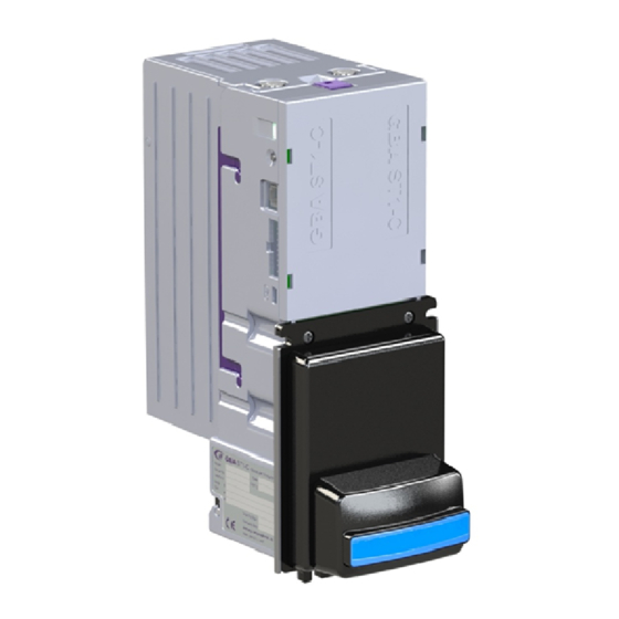
Page 5: Product Architecture
Assembly Note Guide 2.2 Image of product assembly The GBA ST1C product consists of Main Chassis (1) which supports the Top Sensor Assembly (not shown) and Bottom Sensor Assembly (2). Inter-changeable accessories are: (3) Bill Cassette (300 Bills storage) (4) Faceplate / External Note Guides For Faceplate/Note Guide Options refer to section 2.2.4 Note Guide &... - Page 6 2.2.1 Cassette Fitting / Removal To fit a note cassette to the GBA ST1C validator, ensure that the cassette lid is level with purple cassette clip of the GBA ST1C body. Line up the four cassette locating studs with the four location slots in the channel and push the cassette firmly towards the validator body.
- Page 7 2.2.4.1 Up stacker Faceplate 2.2.4.2 Down stacker Faceplate To limit the impact of machine abuse is anticipated, the GBA ST1C unit is secured to the faceplate using four screws. The validator can be mounted either with the faceplate showing at the front of the host machine or with the majority of the faceplate concealed, and just the illuminated note guide visible.
- Page 8 INTERFACE SPECIFICATION 2.2.6 Bar-coded Coupon Sensor The ST1C can be fitted with a sensor for detecting and reading the barcodes on a printed coupon. The sensor uses green light, so it can readily read thermally printed coupons. The sensor can only scan one face of the coupon, so the coupons must be inserted with the barcode facing upwards for the up-stacker arrangement, and facing downwards for the down-stacker.
-
Page 9: Interface Protocols
For NAMA MDB, the interface cable terminates with a 6-way connector. 3.1 NAMA MDB If the GBA ST1C is used in an MDB interface application, then it must be fitted with an optional 20 to 42 Volt power regulator and with opto-isolators on the communication lines, as required by the NAMA MDB specification. -
Page 10: Software Configuration
4.0 - Image illustrating rear of Bottom Sensor Assembly The GBA ST1C can be configured using either the on-board push button or via a Windows based PC package (GBA Talk) or connecting a USB memory device to the USB port. - Page 11 2. Insert the white calibration paper into the validator. It should be presented in the centre of the note path and square to the direction of travel. 3. The ST1C unit will draw-in the paper all the way into the cassette; hold it momentarily before returning it in several short steps.
- Page 12 Program Cards Error on program card Orange Try reprinting the card Program card not Orange Orange Green The program card function is not supported supported by the ST1 Page 12 of 30 Astrosys International Ltd GBA ST1C Operations manual V1_4...
-
Page 13: Pc Based Gba Tools
GBA Global Bill Acceptors 4.2 PC Based GBA Tools The GBA ST1C can also be configured using PC based software, GBA Talk or GBA Service. This software also provides calibration and diagnostic functions. Note: for full instructions on using GBA Talk, refer to the utility’s help file. - Page 14 A Setup USB wizard tool is available within the GBA Talk and GBA Service utilities to help you with this. It is not necessary to have all of these files. You can, for instance, just have a new configuration file on the device and just that will be loaded.
- Page 15 Orange Green Green Too many firmware files found Orange Orange Green Orange Error in firmware file Orange Orange Green Firmware does not support this dataset Orange Orange Orange Page 15 of 30 Astrosys International Ltd GBA ST1C Operations manual V1_4...
-
Page 16: Software Configuration Options
GBA Global Bill Acceptors 4.4 Software Configuration Options: All of the software options below can be set using either the GBA Talk PC software, a configuration file on a USB Mass Storage Device or Program Card facility, as mentioned above. Two kinds of program card are available. -
Page 17: Illuminated Note Guide Patterns
GBA Global Bill Acceptors How to handle a note that is found in the validator at power up: If the ST1C validator detects that there is a note in the note path when it powers up, by default it will return the note to the user. -
Page 18: Electrical Interface Specification
Limiting resistor on RX internal, 560Ω 5.2.3 USB Port The ST1C is compliant as a USB 2.0 full speed host or device and is fitted with a mini-AB socket. Page 18 of 30 Astrosys International Ltd GBA ST1C Operations manual V1_4... -
Page 19: Low Power Mode
The 12 Volts dc power should only be connected to pin 17 of the 20 way connector – pin 16 must not be connected to the supply. When the ST1C wakes up, the 12 Volt bus is energised. Pin 16 can then be used either to provide power to another device or to wake up the host controller. - Page 20 GBA Global Bill Acceptors 6. If a note is returned to the customer, then the ST1C will wait up to 3 seconds for the user to remove it, before powering down. If the note has not been removed, it will send a pulse on the ALARM line, and then go into hibernation.
-
Page 21: Electrical Connections
TXD & RXD can both be connected to the DATA line of the host machine. 2. If the ST1C is used in Low Power Mode, only connect the 12 Volt supply to pin 17. Page 21 of 30... - Page 22 Output – UART, open collector Input – UART, TTL level receive data See the Interface Description Manuals for further details. Page 22 of 30 Astrosys International Ltd GBA ST1C Operations manual V1_4...
-
Page 23: Maintenance
Anti-Static precautions should always be observed when cleaning the GBA ST1C unit. 1. Ensure the power supply to the GBA ST1C unit is switched OFF. 2. Remove the Cassette as described in section 2.2.1 Cassette Fitting / Removal. 3. Lift up the purple Access Latch on the back of the Bottom Sensor Assembly, and gently slide the module out of the Channel Assembly –... -
Page 24: Clearing A Note Jam
GBA Global Bill Acceptors 7.2 Clearing a Note Jam 1. Ensure the power supply to the GBA ST1C unit is switched OFF. 2. Remove the Cassette as described in section 2.2.1 Cassette Fitting / Removal. 3. Lift up the purple Access Latch on the back of the Bottom Sensor Assembly, and gently slide the module out of the Channel Assembly –... -
Page 25: Diagnostics & Troubleshooting
8.1 Image of side view of ST1C showing diagnostic LED 8.1.1 Status LED The GBA ST1C has the facility to communicate validator status by the use of a tri coloured Status LED located on the side of the unit. This enables enhanced diagnostics for the user and for Astrosys personnel when assisting customers over the phone or by email. - Page 26 GBA ST1C Operation Manual GBA Global Bill Acceptors 8.1.2 Illuminated Note guide: The GBA ST1C has a blue illuminated note guide. If the ST1C is out of service, then this will be switched off. 8.1.3 Status LED – Note Reject Codes:...
-
Page 27: Troubleshooting
GBA ST1C Operation Manual GBA Global Bill Acceptors 8.2 Troubleshooting The following information is presented for customers’ guidance in identifying problems with the GBA ST1C. It does not necessarily cover every possible situation. Problem Symptoms Possible Cause Investigate Possible Solution Unit does not work when power is applied 1. -
Page 28: Dimensional Drawings
GBA ST1C Operation Manual GBA Global Bill Acceptors 8.3 Dimensional Drawings 8.3.1 - Upstacker Page 28 of 30 Astrosys International Ltd GBA ST1C Operations manual V1_4... - Page 29 GBA ST1C Operation Manual GBA Global Bill Acceptors 8.3.2 - Downstacker Page 29 of 30 Astrosys International Ltd GBA ST1C Operations manual V1_4...
-
Page 30: Revision History
Steve Lewis Initial issue. 22-Jul-13 Ivan Radojkovic Steve Lewis Added Illustrations and dimensional drawings. Updated text to reflect current ST1C operation. 25-Sep-13 Steve Lewis Steve Lewis Added further information for Low Power Mode. DISCLAIMER Astrosys International Ltd. reserves the right to amend, improve or otherwise change this document or the product referred to herein at any time.
Need help?
Do you have a question about the ST1C and is the answer not in the manual?
Questions and answers