Table of Contents
Advertisement
GBA Global Bill Acceptors
GBA ST1 Operation Manual
GBA ST1
Operation Manual
This document is the copyright of Astrosys International Ltd. and may not be reproduced in total or in part
by any means, electronic or otherwise, without the prior written consent of Astrosys International Ltd.
Page 1 of 37
Astrosys International Ltd
September 2011
ST1 Operations Manual Rev 2.0
Advertisement
Table of Contents
Troubleshooting

Related Manuals for GBA ST1


Summary of Contents for GBA ST1
- Page 1 This document is the copyright of Astrosys International Ltd. and may not be reproduced in total or in part by any means, electronic or otherwise, without the prior written consent of Astrosys International Ltd. Page 1 of 37 Astrosys International Ltd September 2011 ST1 Operations Manual Rev 2.0...
-
Page 2: Table Of Contents
4.2 CCTALK ............................13 4.3 USB ............................13 5.0 SOFTWARE CONFIGURATION.......................15 5.1 On-board Push Button ......................15 5.2 PC Based GBA Tools .........................18 5.3 USB Mass Storage Device......................18 5.4 Software Configuration Options: .....................21 6.0 MECHANICAL INSTALLATION .......................22 7.0 ELECTRICAL INTERFACE SPECIFICATION ..................23 7.1 Power ............................23 7.2 Signal Interface.........................23... -
Page 3: Introduction
The GBA ST1 has been specifically designed for use in Vending applications, however it can also be used in all applications previously served by the GBA vertical stacker range, including Amusement, Parking and Internet Kiosks. -
Page 4: Product Information
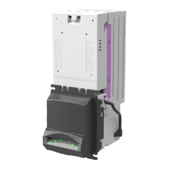
2.2 Product Architecture 2.2 Image of product assembly The GBA ST1 product consists of a Channel Assembly (1) which supports the Top Sensor Assembly (not shown) and Bottom Sensor Assembly (2) which house the mechanics and the software. To complete the unit there are 4 inter-changeable accessories. These are:... -
Page 5: Build Options
2.3.1 Note Cassette 2.3.1 Image of Note Cassette The GBA ST1 includes an integrated, note stacking facility which can be used in either an up, down or horizontal stacking configuration. Notes are stored in a cassette for ease of collection and transportation. - Page 6 The bracket allows the ST1-H to be directly mounted to the cabinet door. The ST1-H can be orientated to stack up or down with the default orientation in the Up-stack direction.
- Page 7 Connections. 2.3.7 Bar-coded Coupon Sensor The ST1 can be fitted with a sensor for detecting and reading the barcodes on a printed coupon. The sensor uses green light, so it can readily read thermally printed coupons. The sensor can only scan one face of the coupon, so the coupons must be inserted with the barcode facing upwards for the down-stacker arrangement, and facing downwards for the up-stacker.
-
Page 8: Mechanical Configuration
GBA ST1 Operation Manual 3.0 MECHANICAL CONFIGURATION 3.1 Up stacker / Down stacker Configuration The GBA ST1 product can be configured for installation in either up or down stacking applications. 3.1.1 Faceplate Fitting / Removal Refer figure 3.1.1 For either up or down stacker configuration, align the faceplate with the 4 locating studs and the 2 clips on the side of the validator. -
Page 9: Horizontal Stacker
To enable the note to traverse correctly in both Horizontal and Top entry formats, a Top Cover is required to be fitted to the normal note entry point of the ST1. The Top Cover can only be fitted when the existing Faceplate and Note Guide have been removed. Firstly you will require the Top Plate Assembly to be inserted into the lower Note Guide socket. -
Page 10: Top Entry Stacker
3.2.2b – Image of Bracket fitting (shows Horizontal bezel) 3.3 Top Entry Stacker Please refer to Product Bulletin "Fitting the GBA ST1-T bracket" for detailed information 3.4 Cassette Options There are 4 different note cassette capacity options of 100, 300 (fitted as standard), 600 and 1000 . - Page 11 3.4.1 Cassette Fitting / Removal To fit a note cassette to the GBA ST1 validator, ensure that the cassette lid is level with purple cassette clip of the GBA ST1 body. Line up the four cassette locating studs with the four location slots in the channel and push the cassette firmly towards the validator body.
- Page 12 (a) Image of lock assembly parts (b) Image of pre-assembled lock (right version shown) (c) Image of lock placement (Left lock pre-assembled, ready for fitting; right lock fitted) Page 12 of 37 Astrosys International Ltd September 2011 ST1 Operations Manual Rev 2.0...
-
Page 13: Interface Protocols
NAMA 6 pin connector. The MDB PSU board is fitted within ST1 and a 6 Pin Connector is accessible at the rear of the Bottom Sensor Assembly, once the vented cover is removed. - Page 14 USB Driver will need to be installed; please contact your regional office for a copy, and specify which version of Windows you are using. The USB port is also used to connect a USB memory device for updating the ST1 firmware, note dataset and configuration.
-
Page 15: Software Configuration
5.0 - Image illustrating rear of Bottom Sensor Assembly The GBA ST1 can be configured using either the on-board push button or via a Windows based PC package (GBA Talk) or connecting a USB memory device to the USB port. - Page 16 2. Insert the white calibration paper into the reader. It should be presented in the centre of the note path and square to the direction of travel. 3. The ST1 unit will draw-in the paper all the way into the cassette; hold it momentarily before returning it in several short steps.
- Page 17 Orange Try reprinting the card Program card not Orange Orange Green The program card function is not supported supported by the ST1 Future Use Orange Orange Red Page 17 of 37 Astrosys International Ltd September 2011 ST1 Operations Manual Rev 2.0...
-
Page 18: Pc Based Gba Tools
Note: the 20 pin harness must contain a 4 pin socket connected to pins 18 and 20. Procedure; 1. Connect the GBA ST1 to the PC by placing the diagnostic harness into the DB9 connector of the PC, and the 4 pin connector into the 4 pin plug of the 20 pin harness. - Page 19 In the root directory you can store one firmware file, one dataset file and one configuration file that matches the country code of the dataset. A Setup USB wizard tool is available within the GBA Talk PC software. It is not necessary to have all of these files. You can, for instance, just have a new configuration file on the device and just that will be loaded.
- Page 20 Green Too many firmware files found Orange Orange Green Orange Error in firmware file Orange Orange Green Firmware does not support this dataset Orange Orange Orange Page 20 of 37 Astrosys International Ltd September 2011 ST1 Operations Manual Rev 2.0...
-
Page 21: Software Configuration Options
GBA ST1 Operation Manual 5.4 Software Configuration Options: All of the software options below can be set using either the GBA Talk PC software, a configuration file on a USB Mass Storage Device or Program Card facility, as mentioned above. Two kinds of program card are available. -
Page 22: Mechanical Installation
With the faceplate (and blanking plate) mounted in the host machine, the GBA ST1 unit fitted with the appropriate note guide is simply clipped into place in the faceplate. Please note that the note guide must be fitted to the validator before inserting the validator into the faceplate. -
Page 23: Electrical Interface Specification
Limiting resistor on RX: internal, 560Ω 7.2.3 USB Connector The ST1 is compliant as a USB 2.0 full speed host or device and is fitted with a mini-AB socket. For Power packs, 12vDC connection should be Centre Positive. Page 23 of 37... -
Page 24: Low Power Mode
6. If a note is returned to the customer, then the ST1 will wait up to 3 seconds for the user to remove it, before powering down. If the note has not been removed, it will send a pulse on the ALARM line, and then go into hibernation. -
Page 25: Electrical Connections
TXD & RXD can both be connected to the DATA line of the host machine. 2. If the ST1 is used in Low Power Mode, only connect the 12 Volt supply to pin 17. Page 25 of 37... - Page 26 50mS on/300ms off. In the fast mode a 50mS/50mS pattern results. Output – UART, open collector Input – UART, TTL level receive data See the Interface Description Manuals for further details. Page 26 of 37 Astrosys International Ltd September 2011 ST1 Operations Manual Rev 2.0...
-
Page 27: Maintenance
Anti-Static precautions should always be observed when cleaning the GBA ST1 unit. 1. Ensure the power supply to the GBA ST1 unit is switched OFF. 2. Remove the Cassette by sliding the cassette clip forwards (away from the cassette) and lifting the cassette away from the GBA ST1 unit. -
Page 28: Clearing A Note Jam
5. Clear the jammed note(s) from the note path. 6. Re-assemble unit and switch the power supply back ON. 9.1 - Images of note path access 9.2 - Image of GBA ST1 in open position for cleaning and Jam Clearance. Page 28 of 37 Astrosys International Ltd September 2011 ST1 Operations Manual Rev 2.0... -
Page 29: Replacing Drive Belts
GBA ST1 Operation Manual 9.3 Replacing Drive Belts 1. Ensure the power supply to the GBA ST1 unit is switched OFF. 2. Remove the GBA ST1 unit from the Faceplate. 3. Remove the Cassette by sliding the cassette clip forwards (away from the cassette) and lifting the cassette away from the GBA ST1 unit. -
Page 30: Diagnostics & Troubleshooting
10.1.1 Diagnostic LED – Bottom Sensor Assembly: The GBA ST1 has the facility to communicate validator status by the use of a tri coloured diagnostic LED located at the rear of the unit. This enables enhanced diagnostics for the user and for Astrosys personnel when assisting customers over the phone or by email. - Page 31 GBA Global Bill Acceptors GBA ST1 Operation Manual 10.1.2 Flashing Note guide: The GBA ST1 has an optional illuminated, tri colour, note guide to further assist in indicating the status of the validator to the end user. Indication Status Flashing Green towards note entry...
-
Page 32: Troubleshooting
GBA Global Bill Acceptors GBA ST1 Operation Manual 10.2 Troubleshooting The following information is presented for customers’ guidance in identifying problems with the GBA ST1. It does not necessarily cover every possible situation. Problem Symptoms Possible Cause Investigate Possible Solution Unit does not work - belt motor does not 1. -
Page 33: Dimensional Drawings
GBA Global Bill Acceptors GBA ST1 Operation Manual 10.3 Dimensional Drawings 10.3.1 - Upstacker Note: All measurements in mm Page 33 of 37 Astrosys International Ltd September 2011 ST1 Operations Manual Rev 2.0... - Page 34 GBA Global Bill Acceptors GBA ST1 Operation Manual 10.3.2 - Downstacker Note: All measurements in mm Page 34 of 37 Astrosys International Ltd September 2011 ST1 Operations Manual Rev 2.0...
- Page 35 GBA Global Bill Acceptors GBA ST1 Operation Manual 10.3.2 – Horizontal Stacker Note: All measurements in mm Page 35 of 37 Astrosys International Ltd September 2011 ST1 Operations Manual Rev 2.0...
- Page 36 GBA Global Bill Acceptors GBA ST1 Operation Manual 10.3.2 – Top Entry Stacker Note: All measurements in mm Page 36 of 37 Astrosys International Ltd September 2011 ST1 Operations Manual Rev 2.0...
-
Page 37: Revision History
Nv 89115 Kowloon USA. Hong Kong Tel: +1 702 643 1600 Tel: +852 2342 6123 Fax: +1 702 643 1717 Fax: +852 2342 6105 E-Mail:sales@astrosystemsinc.com E-Mail: ASF.Sales@astrotech.com.hk Page 37 of 37 Astrosys International Ltd September 2011 ST1 Operations Manual Rev 2.0...
Need help?
Do you have a question about the ST1 and is the answer not in the manual?
Questions and answers