
Related Manuals for GBA ST1C-UL


Summary of Contents for GBA ST1C-UL
- Page 1 GBA ST1C-UL 110 VAC 12Vdc Operation Manual www.TURNSTILES.us / www.entrapass.com / 8641 S. Warhawk Road, Conifer, CO 80433 / 303-670-1099...
-
Page 2: Table Of Contents
CONTENTS INTRODUCTION ..................3 Symbols ........................3 CARE AND TRANSPORT ................4 Transport ........................4 Storage ........................4 Cleaning and Drying ....................4 Unpacking ........................4 SAFETY DIRECTIONS & WARRANTY ............5 General ........................5 Intended Use ......................5 Responsibilities ......................5 Warranty ........................ -
Page 3: Introduction
Please note that all references to “ST1C” in this document mean “ST1C-UL version with integral 100 - 120 Volt AC power regulator”, where applicable. If you have any questions about this or any other GBA and Microcoin products then please visit our web sites at www.globalbillacceptors.com... -
Page 4: Care And Transport
Inspect the Bill Acceptor for potential damage sustained in transit. If any damage is present, return the ST1C-UL into the original packaging and notify the carrier immediately. Send a written intent to file a claim to the delivering carrier within 72 hours from delivery. Send a copy of that letter to the shipper. -
Page 5: Safety Directions & Warranty
Section 3 SAFETY DIRECTIONS & WARRANTY General The following directions should enable the person responsible for the product, and the person responsible for use of the equipment, to anticipate and avoid operational hazards. The person responsible for the product must ensure that all personnel who install and maintain the product understand these directions and adhere to them. -
Page 6: Warranty
Warranty AstroSystems Inc warrants the GBA ST1C-UL Bill Acceptor for a period of one (1) year from the date of purchase. This warranty extends to the original purchaser of the warranted product, and to each transferee owner of the product, during the term of the warranty. -
Page 7: Product Information
Section 4 PRODUCT INFORMATION General Specifications Bill Insertion: Up to 32 bill denominations with 4 way insertion Bill Dimensions: 62 to 70mm wide; 120 to 160 mm long Bill Acceptance Rate: Greater than 95% Cycle Time for Validation and Typically less than 3 seconds Stack: Nominal Cassette Capacity: 300 bills, front or rear access... -
Page 8: Product Architecture
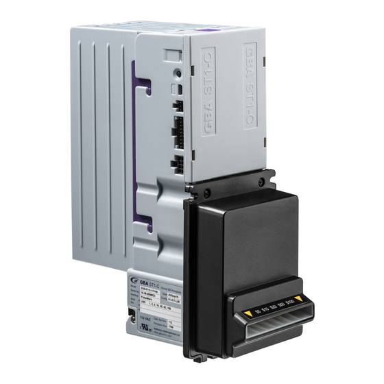
Product Architecture The GBA ST1C-UL bill acceptor is a modular assembly which can be easily accessed for service and support. It consists of a Main Chassis, Faceplate and Bill Guide, Bottom Sensor Housing and a Bill Cassette. There are interchangeable items depending upon the specific application. -
Page 9: Bill Cassette
(showing rear access) (showing front access) style) Remove the cassette by sliding the cassette clip forwards and lifting the cassette from the GBA ST1C-UL unit. Reverse this action to fit the cassette back into place. Page 9 of 25 www.TURNSTILES.us / www.entrapass.com / 8641 S. Warhawk Road, Conifer, CO 80433 / 303-670-1099... -
Page 10: Opening The Bill Cassettes
Opening the Bill Cassettes To access the bills from each cassette Front Access Cassette Rear Access Cassette Squeeze two tabs Press the release button Pull back to open the cassette lid Remove stacked bills Front Access Cassette Front Access Cassette Remove stacked bills Opening lid... -
Page 11: Faceplate Options
Faceplate Options The same faceplate is used for both 66mm bill guides and 70mm bill guides. The design of the bill guide and faceplate is symmetric and it can be mounted in either up or down stacking configuration. Reminder: matching internal bill guides need to be mounted to the Lower Sensor Assembly (refer section 6.2 ). -
Page 12: Connections And User Controls
Connections and User Controls The GBA ST1C includes the following: Item Notes 8 pin port for 100 – 120 Volt AC A connection cable is supplied with the power and signals to the host validator. See section 5.3 for more details machine. -
Page 13: Wiring Looms
Wiring Looms 4.7.1 110VAC operation Bill Acceptor Side Power & Signal Loom Part # ASY-M-141403 Host Side 4.7.2 12Vdc operation 12Vdc Loom Part # ASY-M-141418 Host Side, Unterminated Bill Acceptor Side wires 4.7.3 Programming Loom (optional) Microcoin VAL 364 Bill Acceptor Side Programming Loom Part # ASY-M-141404... -
Page 14: Electrical Interface Specification
Section 5 ELECTRICAL INTERFACE SPECIFICATION ST1C-UL 110VAC is supplied from the mains voltage line; please Caution observe all applicable national and local legislations and regulations during the installation and use of this device. It is the sole responsibility of the customer to familiarize themselves with the product and install it correctly. -
Page 15: 110Vac Power Connector
110VAC Power Connector 5.3.1 9-pin connector Details Connector on the wiring loom: TE Connectivity /Amp Mate-N-Lock 9-pin Female Pin P/N 170362-1, with male crimps P/N 172169-1 Function 120 VAC Neutral Inhibit. 120 VAC Neutral Enable. 120 VAC Hot Enable. 120 VAC Hot Power No Connection 120 VAC Neutral Power Bill Acceptor Relay Contact (Normally Open) -
Page 16: 12Vdc Low Voltage Signal Port
12Vdc Low Voltage Signal Port 5.4.1 18-pin Connector Details Recommended mating connector: TE Connectivity / Amp - 5-102398-7 - Connector, Header, IDC, 2.54mm, 18way View looking at the validator Function Function Out Credit Pulses Out Alarm Out Ready To Send for Serial 12 Volt DC Input Mode (3)(2) -
Page 17: Signal Specifications
5.4.3 Signal Specifications Open Collector outputs: Maximum Open Voltage Maximum Sink Current 50mA @ 12VDC Maximum Output Low Voltage: 0.4VDC Minimum Output High Voltage: 2.4VDC Input low level voltage: 0…. 1V Input high level voltage: 3…..12V (typically 3… 5V) Input pull up to 5V: 21K Ω... -
Page 18: Maintenance & Operation
Ensure the power supply to the GBA ST1C unit is switched OFF. Remove the Cassette. Lift up the purple Access Latch on the back of the Lower Sensor Assembly, and gently slide the module out of the Channel Assembly –... -
Page 19: Lower Sensor Housing
Lower Sensor Housing The lower sensor assembly has an internalised connection to the main chassis, so there is no cable to disconnect. To remove the housing lift the access latch and gently slide back. To refit the assembly, slide it forward until the retaining bar clicks into place. Note that the black internal bill guides must be fitted for either 66 or 70mm applications. -
Page 20: Clearing A Bill Jam
Clearing a Bill Jam Ensure the power supply to the GBA ST1C-UL unit is switched OFF. Remove the Cassette. Lift up the purple Access Latch on the back of the Bottom Sensor Assembly, and gently slide the module out of the Channel Assembly. -
Page 21: Diagnostics & Troubleshooting
7.1 Image of side view of ST1C showing diagnostic LED 7.1.1 Diagnostic LED The GBA ST1C has the facility to communicate validator status by the use of a tri coloured Diagnostic LED located on the side of the unit. This enables enhanced diagnostics for the user and for factory personnel when assisting customers over the phone or by email. -
Page 22: Diagnostic Led - Bill Reject Codes
7.1.2 Diagnostic LED – Bill Reject Codes If a bill is rejected then a flash code is given when the bill is removed (the LED will flash red or orange a number of times): Cause of Bill Rejection Number of flashes Unrecognised bill 1 Red Optical Anti String Gate was triggered... -
Page 23: Troubleshooting
Troubleshooting The following information is presented for customers’ guidance in identifying problems with the GBA ST1C. It does not necessarily cover every possible situation. Problem Symptoms Possible Cause Investigate Possible Solution Unit does not work when power is 1. Power supply not switched on. -
Page 24: Dimensional Drawings
8 DIMENSIONAL DRAWINGS Section Upstacker / Downstacker Page 24 of 25 www.TURNSTILES.us / www.entrapass.com / 8641 S. Warhawk Road, Conifer, CO 80433 / 303-670-1099... -
Page 25: About Us
9 About US Section ABOUT US Company Profile: Established in May, 1989 Quality integrated, high-tech pedestrian and vehicle access security systems, loss control products and designs are the outstanding advantages you receive from TURNSTILES.us. Since 1989, we've proudly offered the best Security Turnstiles to greatly increase the Security of your Agency, Business, or Organization.
Need help?
Do you have a question about the ST1C-UL and is the answer not in the manual?
Questions and answers