Table of Contents
Advertisement
Quick Links
1004 East Illinois Street • Assumption, IL 62510 • 1-217-226-4421
Tools you will need for this installation:
Parts included with the D03-1197-P:
Allen Bradley PowerFlex Model 523 VFD Vector motor controller (Programmed)
Product Description
The Allen Bradley PowerFlex 523 Vector Control VFD drive
control which is a sensorless feedback control based on the "model" of the motor operating parameters
in its memory. As the motor operates, the 523 monitors the output current and compares it to the "models"
and determines from experience what the different current effects mean in terms of the motors
performance. It will then execute the necessary error corrections with the voltage and frequency to
maintain various motor speeds under various loads. Vector drive technology will provide excellent slow
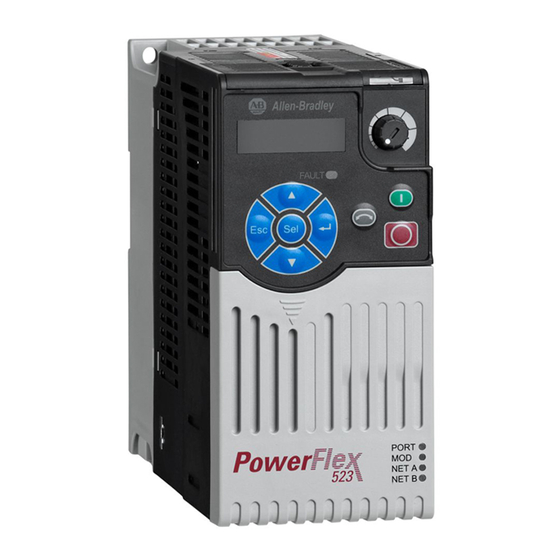
speed motor control.
Figure 2 Allen Bradley PowerFlex 523 Variable Frequency Drive (Vector Control) (D03-1197-P)
A standard (non-vector) VFD drive has no way to compensate or modify its output with the changes in the
load especially when the speed reference gets reduced. This is especially true at speeds below 10 Hz.
Date: 07-17-14
Printed in the U.S.A.
Copyright © 2014 by GSI Group
www.gsiag.com
1/8" Tip screwdriver
Allen Bradley VFD Drive
Phillips tip screwdriver
Figure 1
(See Figure 2)
PNEG-1972
Instructions
Installation Guide for
utilizes vector style motor
PNEG-1972
Page 1 of 7
CN-313720
Advertisement
Table of Contents

Subscribe to Our Youtube Channel
Related Manuals for GSI Group Allen Bradley PowerFlex 523

Summary of Contents for GSI Group Allen Bradley PowerFlex 523
- Page 1 Vector drive technology will provide excellent slow speed motor control. Figure 2 Allen Bradley PowerFlex 523 Variable Frequency Drive (Vector Control) (D03-1197-P) A standard (non-vector) VFD drive has no way to compensate or modify its output with the changes in the load especially when the speed reference gets reduced.
- Page 2 Installation Guide for Allen Bradley VFD Drive Installation Disconnect all power to the panel before proceeding with this installation. Failure to do so could result in serious injury or death. WARNING Locate the existing Allen Bradley 4M VFD drive in the power panel located above the control panel on the dryer.
- Page 3 Installation Guide for Allen Bradley VFD Drive Once the wires are removed remove the existing drive by inserting a screwdriver into the slotted slide catch at the bottom of the drive and push down towards the bottom of the control box to release the drive from the din rail.
- Page 4 Installation Guide for Allen Bradley VFD Drive Figure 7 Drive installed with top module removed for easier view of power connections. Connect the 3 motor wires to T1, T2 and T3. NOTE: Do not mistakenly connect the motor wires to the terminals labeled DC-, DC+/BR+ and/or BR-. Doing so will destroy the drive when power is applied.
- Page 5 Installation Guide for Allen Bradley VFD Drive Figure 9 Old Style AB PowerFlex 4M Wiring Diagram PNEG-1972 Page 5 of 7...
- Page 6 Installation Guide for Allen Bradley VFD Drive Figure 10 New Style AB PowerFlex 523 Wiring Diagram Page 6 of 7 PNEG-1972...
- Page 7 Installation Guide for Allen Bradley VFD Drive Software Setup To ensure the drive will be able to run the motor at minimum speed. Verify and change if necessary the following parameters. Meter roll setup MIN/MAX under Setup->Extended Setup->Diagnostics->Setup Meter rolls. Set the: Minimum = 0 volts Maximum = 10 volts...
Need help?
Do you have a question about the Allen Bradley PowerFlex 523 and is the answer not in the manual?
Questions and answers