Advertisement
Quick Links
Setup Instructions
Contrast
Indicator
Signal
Locked
Strength
Threshold
Output ON
Number
Gap / Label
AUTO Adjust
Mode
Simple Setup Start
in view, press and hold the AUTOSET/GAP
button for two seconds, "Gap Set" will be
displayed when complete. This will result in
a perfect setup 99% of the time. If you have
any false triggers, put the Label in view,
push and hold the AUTOSET/LABEL button
for two seconds, "Label Set" will be
displayed when complete. This two-point
setup will create a new threshold setting
resulting in a more consistent signal span
between web and label.
Note: Sensor is shipped with a protective
plastic covering for the display. Remove
protective covering for clearer viewing.
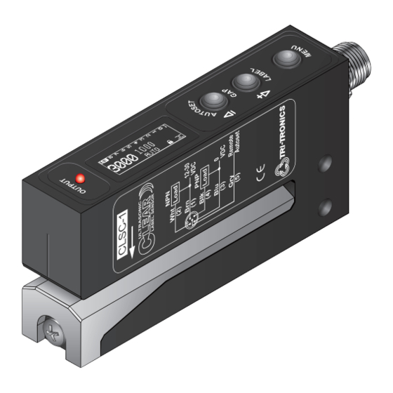
OUTPUT INDICATORS
Red LED illuminates when when outputs are ON
Flashes when short circuit or overload detected
_
AUTOSET/GAP
BUTTON
1. Push and Hold with gap in view for 2 seconds
for AUTOSET.
2. Tap for UP on Contrast Indicator, or reduce
threshold.
3. Change settings in MENU options
+
AUTOSET/LABEL
1. Push and Hold with label in view after GAP
AUTOSET on rare occasions when labels
have multiple layers.
2. Tap DOWN on Contrast Indicator, or increase
threshold.
3. Change settings in MENU options
Put the Gap
BUTTON
Installation Manual
Installation Manual
Label Position
Align Label to Arrow (above)
Place the label web so that it is
centered on the arrow. The arrow is
where the transducers are aligned.
Align Gap to Line (right top)
Place label gap in center of the
sensor using the alignment line as
shown on right. When viewing from
the top of the sensor, use the output
LED to center label gap.
Gentle Tension (right bottom)
Place label webbing so that it slides
along the bottom of the sensor gap
plate. This will ensure a more
consistent setup and performance.
OLED NUMERICAL DISPLAY
1. 1 to 10 bar Contrast Indicator
2. Numerical display for threshold and feedback
number
3. Options Status Display: Button Lock or
Unlock (
in Gap(
4. View Menu Options
MENU BUTTON
1. Push and Hold for 1 second to enter Menu
Options.
2. Tap to scroll through Menu options.
3. Hold during power up for additional Menu
Options; Timers and Factory Diagnostics (or
sensor scope).
P.O. BOX 25135, TAMPA, FL 33622-5135
813-886-4000 / 800-237-0946
ttco.com / info@ttco.com
); auto adjust on/off (AUTO); output
) or on Label (
).
1
Advertisement

Related Manuals for Tri-Tronics M8


Summary of Contents for Tri-Tronics M8
- Page 1 Installation Manual Installation Manual Setup Instructions Label Position Contrast Indicator Signal Locked Strength Threshold Output ON Number Gap / Label AUTO Adjust Align Label to Arrow (above) Mode Place the label web so that it is centered on the arrow. The arrow is ...
- Page 2 - : Gap Set Tap Menu Button Tap 1x : Gap Set Can be used after a Hold Menu on Power Up Tri-Tronics Tampa, FL Hold + : Label Set Tap +/- to Start Tap 2x : Label Set* Gap/Dyn Set to set for more Options www.ttco.com/cls...
- Page 3 Ultrasonic Clear Label Sensor -1 = Standard M12 Connector, see #2 Includes both NPN and PNP Blank = 6’ Cable Select Cable: -1M8 = M8, 4-Pin Connector C = Connector Blank = 6’ (1.8m) Cable NPN/PNP Software Selectable C = Connector M12, 5-Pin...
- Page 4 Set Point and Trigger Point, and all • 1-Point, 2-Point, or Dynamic AUTOSET; CONNECTOR sensor options and modes. manually or remotely. • M12 5-Pin, M8 4-Pin, or 6’ (1.8m) • Red LED Output Indicator– Illuminates THRESHOLD ADJUST Shielded Cable when the sensor’s output transistors are •...
Need help?
Do you have a question about the M8 and is the answer not in the manual?
Questions and answers