
Subscribe to Our Youtube Channel
Related Manuals for Pichler LG 100 UP


Summary of Contents for Pichler LG 100 UP
- Page 1 OPERATING AND INSTALLATION MANUAL FLUSH-MOUNTED UNIT LG 100 UP COMFORT VENTILATION Systematic ventilation.
-
Page 2: Table Of Contents
OPERATING AND INSTALLATION MANUAL FLUSH-MOUNTED UNIT LG 100 UP PAGE 2 Contents General 1. Introduction Page 4 2. General Page 4 Users 2.1. VERSION PAGE 5 2.1.1. SINGLE-ROOM APPLICATION PAGE 5 2.1.2. MULTI-ROOM APPLICATION PAGE 6 2.2. INSTALLATION VARIANT WITH CONNECTION TO THE REVEAL PAGE 7 2.2.1. - Page 3 OPERATING AND INSTALLATION MANUAL FLUSH-MOUNTED UNIT LG 100 UP PAGE 3 Specialist personnel - assembly/installation 13. Transport, storage and disposal Page 24 13.1. TRANSPORT, STORAGE AND PACKAGING PAGE 24 13.2. DISPOSAL PAGE 24 14. Technical specifications Page 25 14.1. UNIT SET-UP AND DIMENSIONS PAGE 25 14.2.
-
Page 4: Introduction
1. Introduction Dear customer, Thank you for choosing the decentralised compact ventilation unit LG100 from PICHLER. To operate your compact ventilation unit safely, properly and economically, please read this manual carefully and follow the in- structions provided. Keep this operating manual in a safe place and readily available at all times. These units are subject to ongoing improvement and further development. -
Page 5: Version
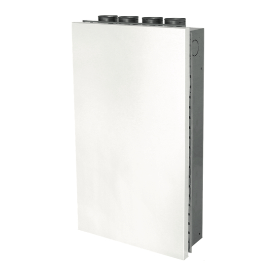
OPERATING AND INSTALLATION MANUAL FLUSH-MOUNTED UNIT LG 100 UP PAGE 5 2.1. Version 2.1.1. SINGLE-ROOM APPLICATION The compact ventilation unit LG100 in flush-mounted design consists of a flush-mounted housing (3) and a ventilation unit as slide-in module (2). The ventilation unit is closed with a design front (1) at its front side. The outdoor air and exhaust air connections are led outside through a wall duct (5). -
Page 6: Multi-Room Application
OPERATING AND INSTALLATION MANUAL FLUSH-MOUNTED UNIT LG 100 UP PAGE 6 2.1.2. MULTI-ROOM APPLICATION The compact ventilation unit LG100 in flush-mounted design consists of a flush-mounted housing (3) with pre-assembled connectors and a ventilation unit as slide-in module (2). The ventilation unit is closed with a design front (1) at its front side. The outdoor air and exhaust air connections are led outside through a wall duct (5). -
Page 7: Installation Variant With Connection To The Reveal
OPERATING AND INSTALLATION MANUAL FLUSH-MOUNTED UNIT LG 100 UP PAGE 7 2.2. Installation variant with connection to the reveal 2.2.1. SINGLE-ROOM APPLICATION The compact ventilation unit LG100 in flush-mounted design for reveals consists of a flush-mounted housing (3) and a ventilation unit as slide-in module (2). -
Page 8: Multi-Room Application
OPERATING AND INSTALLATION MANUAL FLUSH-MOUNTED UNIT LG 100 UP PAGE 8 2.2.2. MULTI-ROOM APPLICATION The compact ventilation unit LG100 in flush-mounted design for reveals consists of a flush-mounted housing (3) with pre-assembled connectors and a ventilation unit as slide-in module (2). -
Page 9: Overview Of Components
The decentralised compact ventilation unit LG100 is controlled easily and intuitively via a pushbutton that is positioned directly on the unit, or via the PICHLER APP. Therefore the unit comes with a WLAN connection as a standard feature. Optionally you can additionally connect an external control unit via cable connection. -
Page 10: Stipulations For Operation With Fireplaces
OPERATING AND INSTALLATION MANUAL FLUSH-MOUNTED UNIT LG 100 UP PAGE 10 In order to prevent uncontrolled condensate formation in the unit, continuous operation at outdoor temperatures below 0 °C with an extract humidity of more than 60% must be avoided (e.g. private spa area). -
Page 11: Warranty
OPERATING AND INSTALLATION MANUAL FLUSH-MOUNTED UNIT LG 100 UP PAGE 11 The manufacturer accepts no responsibility for any damage due to: • non-compliance with the safety, operating and servicing instructions given in this operating and installation manual. • the installation of spare parts that have not been supplied by the manufacturer, the responsibility for the use of such spare parts being fully borne by the system builder/installer. -
Page 12: Safety Regulations
OPERATING AND INSTALLATION MANUAL FLUSH-MOUNTED UNIT LG 100 UP PAGE 12 5.2. Safety regulations Installation, initial start-up, maintenance and repairs must only be carried out by an authorised specialist company. Over and above this operating and installation manual, local and national regulations and standards shall also apply to the operation of this unit without limitation. -
Page 13: Plant Operation
OPERATING AND INSTALLATION MANUAL FLUSH-MOUNTED UNIT LG 100 UP PAGE 13 Before opening the unit and when carrying out work on the unit, e.g. maintenance work and repairs, the unit must be isolated from the mains (all poles disconnected) and secured against being switched back on for the duration of the work. -
Page 14: Customer Service
– when the time interval is reached • standard operation via pushbutton on the unit, WLAN interface for control via the PICHLER APP and for remote access via PICHLER Connect and optionally with the control unit “MINI” for setting the basic functions. -
Page 15: How To Operate The Unit
OPERATING AND INSTALLATION MANUAL FLUSH-MOUNTED UNIT LG 100 UP PAGE 15 8. How to operate the unit The ventilation unit can be operated without a control unit via a button on the bottom side of the unit. A green LED indicates the different operating states of the ventilation unit. -
Page 16: Mini Control Unit
OPERATING AND INSTALLATION MANUAL FLUSH-MOUNTED UNIT LG 100 UP PAGE 16 9. MINI control unit 9.1. Functions The following compact ventilation unit functions can be indicated and configured with the MINI control unit: • Ventilation level of the compact ventilation unit •... -
Page 17: Operation Via Pichler App And Pichler Connect
Operational safety: remote access allows the PICHLER customer service to respond quickly and easily in the event of faults. connect. 10.3. Data protection When you have installed the PICHLER APP and establish a connection to the device, we assume that you accept our current data privacy statement (see: www.pichlerluft.at/datenschutz.at). Changes reserved... -
Page 18: Create An Account
OPERATING AND INSTALLATION MANUAL FLUSH-MOUNTED UNIT LG 100 UP PAGE 18 10.4. Create an account When the Access Point mode is active, the ventilation unit is visible via the WLAN settings of the smartphone. Select the network “LG100AHU” and enter the password “Pichlerluft1234”. - Page 19 OPERATING AND INSTALLATION MANUAL FLUSH-MOUNTED UNIT LG 100 UP PAGE 19 In order to connect the ventilation unit with the Internet router, you have to enter the network name (WIFI-SSID), the WiFi pass- word and the WiFi encryption. Then press “Accept”. The direct...
-
Page 20: Error & Warning Messages
OPERATING AND INSTALLATION MANUAL FLUSH-MOUNTED UNIT LG 100 UP PAGE 20 11. Error & warning messages 11.1. LED on the ventilation unit The error messages of the compact ventilation unit are indicated by red LED flashing patterns on the bottom side of the ventilation unit. -
Page 21: Filter Service
OPERATING AND INSTALLATION MANUAL FLUSH-MOUNTED UNIT LG 100 UP PAGE 21 12. Filter service Each time the filters are maintained, always all three filters must be replaced. 12.1. MINI control unit filter message When the filter lifetime has expired (factory default: 6 months), the control unit indicates the necessity of a filter check via the LED provided for this purpose (bottom left), which is then lit yellow permanently. -
Page 22: Filter Change
55% 40LG0500007A 12.5. Procedure for the filter change 1. Filter message via flash code on the unit, on the MINI control unit, or via the Pichler app 2. Set the unit to Standby. 3. Remove the design front 4. Remove the filter covers by pressing the latches positioned at the sides towards the inside. - Page 23 OPERATING AND INSTALLATION MANUAL FLUSH-MOUNTED UNIT LG 100 UP PAGE 23 Push the design front upwards Remove the design front Open the filter cover Remove the filter cover Remove the filter All 3 filters removed Changes reserved...
-
Page 24: Specialist Personnel - Assembly/Installation
OPERATING AND INSTALLATION MANUAL FLUSH-MOUNTED UNIT LG 100 UP PAGE 24 Specialist personnel - assembly/installation 13. Transport, storage and disposal Any transport damage and/or missing parts must be reported immediately in writing to the forwarder or supplier. 13.1. Transport, strorage and packaging The compact ventilation unit is delivered in a transport packaging. -
Page 25: Technical Specifications
OPERATING AND INSTALLATION MANUAL FLUSH-MOUNTED UNIT LG 100 UP PAGE 25 14. Technical specifications 14.1. Unit set-up and dimensions rear view 80 8 A(1:5) ·� C l ) C C ) C ) C ) Cl D C 1 Supply air (SUP) �... -
Page 26: System Diagram
The ventilation unit is regulated in a demand-oriented fashion via the VOC/eCO2 sensor system integrated into the ventilation unit. 8. Controller The ventilation unit can be optionally controlled by means of a push button on the unit, via Pichler- APP, or via the “MINI” control panel. 9. Outdoor air flap Closes the outdoor air connection of the unit when the unit is switched off. -
Page 27: Safety Devices
OPERATING AND INSTALLATION MANUAL FLUSH-MOUNTED UNIT LG 100 UP PAGE 27 14.3. Safety devices To ensure safe operation of the system, safety devices and covers must by no means be rendered inoperative; nor may measures be taken to bypass or dismantle them. -
Page 28: Sound Data
OPERATING AND INSTALLATION MANUAL FLUSH-MOUNTED UNIT LG 100 UP PAGE 28 Materials and components Inner part EPP and galvanised steel sheets Design front Steel sheet, galvanised and powder-coated Heat exchanger Enthalpy counterflow heat exchanger with a polymer membrane Fans EC radial fans... -
Page 29: Control
OPERATING AND INSTALLATION MANUAL FLUSH-MOUNTED UNIT LG 100 UP PAGE 29 15. Control 15.1. Frost protection with preheating battery Optionally, the ventilation unit LG 100 is available with an integrated electrical PTC preheating battery. With activated preheating- battery the cold outdoor air is preheated via the electrical PTC heating element. This operating mode provides a guaranteed balanced air volume flow between supply air and extract air. -
Page 30: Voc/Eco2 Control
OPERATING AND INSTALLATION MANUAL FLUSH-MOUNTED UNIT LG 100 UP PAGE 30 15.4. VOC/eCO2 control The room air quality is measured via VOC and eCO2 sensors, and the air volume flow is controlled in a demand-oriented fashion. In the automatic mode, the ventilation unit regulates the air volume flow as a function of the air quality (VOC) or the eCO2 values on a needs-based basis. -
Page 31: Mounting
OPERATING AND INSTALLATION MANUAL FLUSH-MOUNTED UNIT LG 100 UP PAGE 31 16. Mounting 16.1. Installation of the slide-in module in the flush-mounted housing Before inserting the slide-in module into the flush-mounted housing, the cables must be threaded by specialist personnel responsible. - Page 32 OPERATING AND INSTALLATION MANUAL FLUSH-MOUNTED UNIT LG 100 UP PAGE 32 Then the four screws from the slide-in module for fastening on the flush-mounted housing are removed. Keep the screws safe. The slide-in module can then be inserted into the flush-mounted housing by means of an assembly aid.
- Page 33 OPERATING AND INSTALLATION MANUAL FLUSH-MOUNTED UNIT LG 100 UP PAGE 33 In order to provide for a correct insertion position, the slide-in module must be inserted into the flush-mounted housing up to the point that the assembly aids touch the interior plaster closely.
- Page 34 OPERATING AND INSTALLATION MANUAL FLUSH-MOUNTED UNIT LG 100 UP PAGE 34 Assembly aids must touch the interior plaster closely When the assembly aids touch the interior plaster, the correct position is ensured and the slide-in module is fastened to the four mounting brackets of the flush-mounted housing using the screws removed previously.
-
Page 35: Electrical Connection
OPERATING AND INSTALLATION MANUAL FLUSH-MOUNTED UNIT LG 100 UP PAGE 35 16.2. Electrical connection Electrical connection and work on electrical components may only be carried out by authorised electricians. Before working on the control board, the unit must be isolated from the mains (all poles) and protected from being switched back on. - Page 36 OPERATING AND INSTALLATION MANUAL FLUSH-MOUNTED UNIT LG 100 UP PAGE 36 Optionally, the ventilation unit can be controlled via the MINI control unit or via modbus RTU (GLT connection). A digital input is provided as “External off” (contact: NC or NO contact) or at “External ventilation level 3” (contact as NO contact), depending on the configuration. The standard setting configured for the digital input is “External ventilation level 3”.
-
Page 37: Adjusting The Air Regulation Sheets
OPERATING AND INSTALLATION MANUAL FLUSH-MOUNTED UNIT LG 100 UP PAGE 37 16.3. Adjusting the air regulation sheets The LG 100 as flush-mounted type allows for single-room and multi-room application. For this purpose it is essential to adjust the air regulation sheets according to the application. The air regulation sheets are located above the supply air and extract air filters, respectively. -
Page 38: Multi-Room Application
OPERATING AND INSTALLATION MANUAL FLUSH-MOUNTED UNIT LG 100 UP PAGE 38 16.3.2. MULTI-ROOM APPLICATION In order to be able to adjust the air regulation sheets, the screws must be unscrewed first. Air regulation sheet - fully opened To adjust the correct air volume flow for a multi-room application, the air regulation sheet must be adjusted and the air volume flow must be measured on the outlet valve of the corresponding adjoining rooms. -
Page 39: Installation Of The Design Front
OPERATING AND INSTALLATION MANUAL FLUSH-MOUNTED UNIT LG 100 UP PAGE 39 16.4. Installation of the design front In order to close the unit, the design front must be fastened at the retention points of the slide-in module. For this purpose, the cover front is pressed against the wall and slid into the retention points top down. -
Page 40: Specialist Personnel - Commissioning
OPERATING AND INSTALLATION MANUAL FLUSH-MOUNTED UNIT LG 100 UP PAGE 40 Specialist personnel - commissioning 17. Maintenance and cleaning 17.1. Safety instructions For all cleaning or servicing work on the ventilation unit, always pull the mains plug or fully disconnect the unit from the mains (all poles)! Further installation and system components must be maintained and cleaned in compliance with specifications and instructions. -
Page 41: Cleaning The Equipment Housing Inside
OPERATING AND INSTALLATION MANUAL FLUSH-MOUNTED UNIT LG 100 UP PAGE 41 2.) Removing the heat exchanger: Removing the heat exchanger 17.4. Cleaning the equipment housing inside We recommend cleaning at least once a year, depending on the level of soiling. Handle the device surface with care when cleaning it. -
Page 42: Service Table
OPERATING AND INSTALLATION MANUAL FLUSH-MOUNTED UNIT LG 100 UP PAGE 42 17.5. Service table In order to document maintenance works, this table must be completed after performance of works on the unit: System commissioned by: Date Maintenance work (e.g. filter change) - Page 43 OPERATING AND INSTALLATION MANUAL FLUSH-MOUNTED UNIT LG 100 UP PAGE 43 Changes reserved...
-
Page 44: Commissioning
OPERATING AND INSTALLATION MANUAL FLUSH-MOUNTED UNIT LG 100 UP PAGE 44 18. Commissioning The ventilation system must be complete, connected and ready for operation before it is put into operation for the first time. The unit can be put into operation and system settings can be configured only when all work on the system is complete. -
Page 45: Error Description
OPERATING AND INSTALLATION MANUAL FLUSH-MOUNTED UNIT LG 100 UP PAGE 45 19. Error description 19.1. Description of errors indicated by the MINI control unit Error descriptions for the corresponding light patterns are provided in the following table. Errors can be located precisely using the service software (available to specialist personnel only). -
Page 46: Description Of Errors Indicated By The Ventilation Unit
OPERATING AND INSTALLATION MANUAL FLUSH-MOUNTED UNIT LG 100 UP PAGE 46 19.2. Description of errors indicated by the ventilation unit Error descriptions for the corresponding light patterns are provided in the following table. Errors can be located precisely using the service software (available to specialist personnel only). -
Page 47: Spare Parts And Accessories
OPERATING AND INSTALLATION MANUAL FLUSH-MOUNTED UNIT LG 100 UP PAGE 47 21. Spare parts and accessories Only original spare parts may be installed or used for replacements and repairs. Dependable operation is ensured only if original spare parts are used! 21.1. - Page 48 Responsible for the content J. PICHLER Gesellschaft m.b.H. Photos: Ferdinand Neumüller, archive J. PICHLER Gesellschaft m.b.H. | Text: J. PICHLER Gesellschaft m.b.H. All rights reserved | All images are symbolic illustrations | Subject to change without notice | Version: 05/2021 EH J.
Need help?
Do you have a question about the LG 100 UP and is the answer not in the manual?
Questions and answers