Table of Contents
Advertisement
Quick Links
Visit website for available
languages of this document.
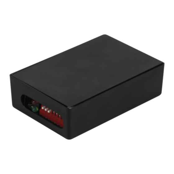
DESCRIPTION
1. Red LED
2. Green LED
3. DIP switches
1
2
TECHNICAL SPECIFICATIONS
Power Supply:
Operating Frequency:
Power Consumption:
Output:
Max. Voltage (relay contact):
Max. Current (both relay contcats):
PRECAUTIONS
‰
Shut off all power going to header before attempting any wiring procedures.
‰
The door control system and the header cover profile must be correctly grounded.
‰
Maintain a clean and safe environment when working in public areas.
Constantly be aware of pedestrian traffic around the door area.
‰
Always stop pedestrian traffic through the doorway when performing tests that may result in unexpected
‰
reactions by the door.
‰
ESD (electrostatic discharge): Circuit boards are vulnerable to damage by electrostatic discharge. Before
handling any board, ensure you dissipate your body's ESD charge.
‰
Always check placement of all wiring before powering up to ensure that moving door parts will not catch
any wires and cause damage to equipment.
‰
Ensure compliance with all applicable safety standards (i.e. ANSI A156.10) upon completion of installation.
‰
DO NOT attempt any internal repair of the components. All repairs and/or component replacements must be
performed by BEA, Inc. Unauthorized disassembly or repair:
1. May jeopardize personal safety and may expose one to the risk of electrical shock.
2. May adversely affect the safe and reliable performance of the product resulting in a voided warranty.
‰
Always test the proper operation of the installation before leaving the premises.
‰
Only trained and qualified personnel are recommended to install and set up the sensor.
75.0061.07 LO-21 20190318
75.0061.07 LO-21 20190318
3
12 – 24 VAC / 15 – 24 VDC
4 MHz (microprocessor)
10 mA at rest (50 mA max)
2 x SPST relays
60 VDC, 120 VAC
2A DC, 0.5A AC
Specifications are subject to change without prior notice.
All values measured in specific conditions.
Lock-out relay for swing doors
with overhead presence sensors
ANSI/BHMA 156.10-2005 requires the use of a
sensor or photobeam on the swing side of the
door when using a header-mounted, safety
sensor (e.g. Bodyguard or DK12).
information, reference the ANSI 156.10 standard.
LO-21
(US version)
For more
Page 1 of 4
Page 1 of 4
Advertisement
Table of Contents

Subscribe to Our Youtube Channel
Related Manuals for BEA LO-21


Summary of Contents for BEA LO-21
- Page 1 ‰ DO NOT attempt any internal repair of the components. All repairs and/or component replacements must be performed by BEA, Inc. Unauthorized disassembly or repair: 1. May jeopardize personal safety and may expose one to the risk of electrical shock.
- Page 2 • Power the safety beams with the same transformer that is used for the LO-21. • The black/white striped wire is not used and should be taped off. • The gray and purple wires of the LO-21 go to the NO and COM dry contacts of the safety beams. HYDRAULIC UNIT / AC MOTOR If AC voltage is >...
- Page 3 1. Upon powering, verify red LED when door is in closing cycle. If it does not: - DC units: Reverse the red and black wires from LO-21 to motor. - AC units: Verify AC power is being switched on and off at point of connection for red and black wires.
- Page 4 BEA strongly recommends that installation and service technicians be AAADM-certifi ed for pedestrian doors, IDA-certifi ed for doors/gates, and factory- trained for the type of door/gate system.
Need help?
Do you have a question about the LO-21 and is the answer not in the manual?
Questions and answers