
Subscribe to Our Youtube Channel
Related Manuals for urmet domus Elkron C420


Summary of Contents for urmet domus Elkron C420
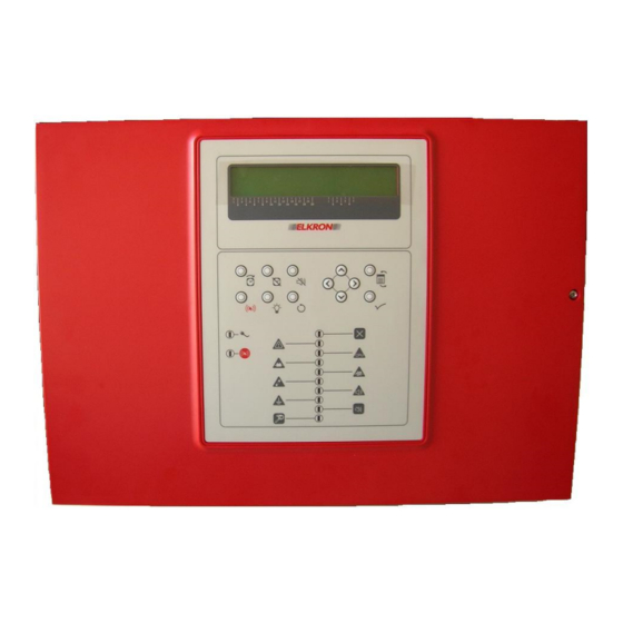
- Page 1 C420 4 – 20 zones Conventional control panel 0051 DS80SC86-005D LBT80743 1/28 Installazione MP508...
- Page 2 The information contained in this document has been collected and controlled carefully. However, the company cannot be held responsible for any possible errors and omissions. The company reserves the right to make, at any time and without warning, improvements and modifications to the products described in this manual.
-
Page 3: Table Of Contents
TABLE OF CONTENTS GENERAL DESCRIPTION ................................4 MAIN CHARACTERISTICS ..............................4 OPTIONS ....................................4 CE LABELS AND RELATED DOCUMENTATION ........................ 5 GENERAL SAFETY RULES ................................ 6 SAFETY OF PEOPLE ................................6 2.1.1 Installation, start up and maintenance operations ......................6 2.1.2 Power supply insulating device ............................ -
Page 4: General Description
1 GENERAL DESCRIPTION 1.1 MAIN CHARACTERISTICS C420 is a modular conventional control panel which can handle from 4 (basic configuration) up to max 20 detection circuits (via optional circuit modules ML420) where it is possible to connect up to 512 points. Each circuit covers a zone which can house up to 32 conventional points (the control panel, though, has to be compliant with the constraint of max 512 total points in the field). -
Page 5: Ce Labels And Related Documentation
1.3 CE LABELS AND RELATED DOCUMENTATION In compliance with the requirements of the product standards EN54-2 and EN54-4, the “CE” label containing all the required information is reported below: 0051 0051 is a trademark of URMET S.p.A. Via Bologna, 188/C - 10154 Torino - Italy 0051-CPR-0382 DoP n. -
Page 6: General Safety Rules
2 GENERAL SAFETY RULES 2.1 SAFETY OF PEOPLE A few general safety instructions to be observed are reported below. 2.1.1 Installation, start up and maintenance operations Only skilled personnel is allowed to carry out the installation phase, the search of faults and, in general, any intervention on the control panel or the system. -
Page 7: Product Safety
2.2 PRODUCT SAFETY The control panel must undergo a permanent installation. Please, look at the relevant section in this manual. • Do not place the control panel next to liquids or in an excessively humid environment; • do not let liquids or foreign matter go inside the equipment; •... -
Page 8: Installation And Connections
3 INSTALLATION AND CONNECTIONS 3.1 ELEMENTS INCLUDED The following elements are provided with the control panel in the same package: • 4 resistors (3300Ω value) for detection circuit termination (end of line resistors) • 1 resistor (3300Ω value) for siren output circuit termination (end of line resistor) •... -
Page 9: Internal Layout Of The C420 Modules
3.3 INTERNAL LAYOUT OF THE C420 MODULES The control panel is composed of several modules and boards properly connected among them: • Power supply unit (AC/DC) • CPU board • Command and Control module (MCC) • Display module • Up to 4 optional ML420 circuit modules – 4 conventional detection circuits and 4 relay outputs per module •... -
Page 10: Ac/Dc Power Supply Unit
3.3.1 AC/DC power supply unit The power supply unit, located on the left side of the mechanical chassis, converts the AC mains in a DC voltage suitable to power the control panel on. The terminals for the connection with the AC mains are located on the module as indicated below. Figure 2 –... -
Page 11: Cpu Board
3.3.2 CPU board The CPU board, located on the foreground inside the box, manages the control panel by communicating with the modules it is composed of. Several connectors are placed on this board. A few of them are permanently used; other ones are available for connecting optional modules. -
Page 12: Command And Control Module
3.3.3 Command and control module The Command and Control module (MCC), located on the back of the chassis, handles several sections and notifies to the CPU board any malfunctioning and alarm conditions. This module is composed of the following sections: •... - Page 13 MCC module terminals RS485 A+ RS485 A+ output for connection to the printer module and the LCD annunciator RS485 B- RS485 B- output for connection to the printer module and the LCD annunciator 24V⎓ auxiliary external power supply unit 1 positive input – the supervision of this input EXT PS1 + depends on the JP3 jumper (pin 5,6) of the CPU board EXT PS1 -...
-
Page 14: Batteries Installation
MCC module jumpers Not inserted Normal working mode (*) If the control panel is powered OFF and the batteries are connected, when this Inserted jumper is inserted the control panel is powered ON directly by the batteries Zone 1 alarm relay – Normally Closed dry contact Zone 1 alarm relay –... -
Page 15: Ml420 Optional Module
3.5 ML420 OPTIONAL MODULE The ML420 optional module allows the control panel to increase the number of detection circuits. Each module adds 4 conventional detection circuits and 4 zone relay outputs. The control panel can be equipped with up to 4 ML420 modules connected in series. The terminals and connectors of this module are described below. -
Page 16: Ml420 Installation
3.5.1 ML420 installation The following components can be found in the package of ML420: • 4 3300Ω end of line resistors for detection circuit termination • 2 female plug terminals • 1 plastic spacer • 2 fixing screws • 1 toothed washer •... -
Page 17: Mr420 Optional Module
3.6 MR420 OPTIONAL MODULE The optional module MR420 allows the control panel to expand its outputs by adding 4 supervised siren outputs. The module must be connected to the Command and Control module. The connectors and terminals of the module are reported below: Figure 7 –... -
Page 18: Mr420 Installation
3.6.1 MR420 installation The following components are provided along with the MR420 module, in the same package: • 4 3300Ω end of line resistors for siren output termination • 2 plastic spacers • 1 metallic hexagonal spacer • 1 toothed washer In order to install the MR420 optional module, please proceed as indicated below: •... -
Page 19: System Start Up
3.8 SYSTEM START UP After having carried out the electrical connections, the control panel can be powered on and activated as follows: • Connect the batteries terminals. • Close the plastic cover of the control panel. • Power supply the control panel via the AC mains. •... -
Page 20: Commands And Indicators
4 COMMANDS AND INDICATORS 4.1 KEYBOARD The control panel is equipped with a 12 keys keyboard located on the front panel. For further information, please refer to the programming manual. Icon Name Function This key only affects running siren output activation delays; INCREASE when this key is pressed, each delay is incremented by 1 DELAY... -
Page 21: Led Indicators
4.2 LED INDICATORS The control panel is equipped with 12 LEDs which notify alarms, faults and exclusions. For further information, please refer to the programming manual. Icon Name Colour Function Steady ON: the control panel is power supplied through the AC mains. AC / BATTERY GREEN Blinking: the control panel is power supplied through... -
Page 22: Inputs And Outputs
5 INPUTS AND OUTPUTS 5.1 AUXILIARY POWER SUPPLY UNITS INPUTS The control panel is equipped with 2 inputs used to connect 24V⎓ auxiliary power supply units which can power on the control panel if the AC mains is missing. This feature is useful when the AC mains is missing and the control panel is required to work for long time. -
Page 23: Technical Characteristics
6 TECHNICAL CHARACTERISTICS 6.1 DETECTORS The detectors to be connected to the control panel must be characterized by an average current consumption in idle condition lower than 100μA and a current consumption in alarm condition of 23mA at 20V⎓. The manual call points must have a current consumption in alarm condition of 50mA at 20V⎓... -
Page 24: Supervised Siren Output
6.5 SUPERVISED SIREN OUTPUT Siren output Output voltage 24V⎓ End of line resistor 3300Ω Max available current 500mA Protection fuse (F2) 5x20 – 250V F500mA 6.6 SUPERVISED SIREN OUTPUTS – MR420 Siren outputs Output voltage 24V⎓ End of line resistor 3300Ω... -
Page 25: Mechanical - Environmental Conditions
6.10 MECHANICAL – ENVIRONMENTAL CONDITIONS Figure 8 – Dimensions and hole template Mechanical – Environmental conditions Dimensions (L x H x D) mm 490 x 350 x 149 Weight (batteries not included) 5.7 Kg max Material Lid in ABS – Back in painted metal, FeP01 -5°... -
Page 26: Electrical Connections
7 ELECTRICAL CONNECTIONS SIREN SIREN OUTPUT OUTPUT C420 / MR420 C420 / MR420 INT-SONG54 MODULE END OF SIR+ LINE RESISTOR SIR- SIREN / VISUAL SIREN / VISUAL MODULO SONG54 SIREN / VISUAL Figure 9 – Examples of connection of the siren output Check which connection type can be used, based on the siren/plate. - Page 27 Figure 11 – Connection of the points to the detection circuit C420 Installation Manual...
- Page 28 ELKRON ELKRON is a trademark of URMET S.p.A. Tel. +39 011.3986711 - Fax +39 011.3986703 Via Bologna, 188/C - 10154 Torino (TO) – Italy Milano: Tel. +39 02.334491- Fax +39 02.33449213 www.urmet.com www.elkron.com – mail to: info@elkron.it Made in ITALY C420 Installation Manual...
Need help?
Do you have a question about the Elkron C420 and is the answer not in the manual?
Questions and answers