
Related Manuals for urmet domus 1061/006A


Summary of Contents for urmet domus 1061/006A
- Page 1 Mod. 1061 DS1061-036A LBT20130 MULTIFUNCTION CONTROL PANEL 1061/006A INSTALLATION AND PROGRAMMING MANUAL...
-
Page 2: Table Of Contents
SYSTEM ARCHITECTURE ......................6 SYSTEM DESCRIPTION AND ITS EXPANSIONS ..............6 SYSTEM COMPONENTS ......................7 1.3.1 1061/006A Control panel ......................7 1.3.2 Management keypad with Led – 1061/025 ................8 1.3.3 Electronic key reader – 1061/334 and 1061/335 ..............8 1.3.4... - Page 3 ADDITION OF A CONTROL PANEL OPTIONAL DEVICE............58 BATTERY REPLACEMENT ....................... 59 CLEANING ..........................59 TECHNICAL CHARACTERISTICS ..................... 60 1061/006A CONTROL PANEL....................60 1061/025 MANAGEMENT KEYPAD ..................61 ELECTRONIC KEY READER ....................61 PROXIMITY READER........................ 61 1061/002 PSTN TELEPHONE COMMUNICATOR..............61 1061/458 GSM MODULE ......................
- Page 4 1061/012 SPEECH SYNTHESIS BOARD ................. 62 1061/013 ENVRONMENTAL LISTENING MODULE/MESSAGES REPEATER ....... 62 EXAMPLE OF CONNECTION WITH NC LINES................. 63 FACTORY SETTINGS ........................65 ANNEX – SYSTEM FINAL CONFIGURATION .................... 66 DS1061-036A...
- Page 5 WARNING! The operating mode this manual explains is compliant with the requests provided in EN50131 standard. In order to enable this operating mode, the yellow jumper JP4 must be open (see figure 22). Please see paragraph 4.2.4 Selecting the control panel operating mode for more details.
-
Page 6: General Description
GENERAL DESCRIPTION The 1061 burglar system has been designed and developed for small-sized systems, used for example in residential areas and little companies (offices, shops, workshops and little factories) and can be easily adapted for different requirements. Maximum compactness, flexibility and safety are the system main characteristics; its installation, use and programming procedures are user-friendly for both installer and users. -
Page 7: System Components
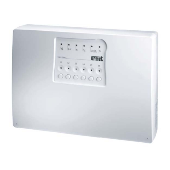
SYSTEM COMPONENTS 1.3.1 1061/006A Control panel The control panel 1061/006A manages the whole system by means of a microprocessor. Its features and performance are as follows: No. of Zones for free No. of inputs for alarm detectors Alarm outputs no. -
Page 8: Management Keypad With Led - 1061/025
1.3.2 Management keypad with Led – 1061/025 The management keypad with LEDs allows to arm and disarm the system, also partially, by signalling the zones state on dedicated LEDs, with alarms storage and failures signalling. The keypad manages up to 10 codes (from 4 to 6 digits) and is equipped with an internal buzzer, auxiliary input and tamper input. -
Page 9: Electronic Key - 1061/332
1.3.5 Electronic key – 1061/332 Programmable electronic key, to be used with the electronic key reader. 1.3.6 Transponder key – 1056/032 Programmable transponder key, to be used with the proximity reader. 1.3.7 PSTN telephone communicator – 1061/002 The PSTN telephone communicator can be programmed with the control panel function keys or with PC and allows to: •... -
Page 10: Informative And Environmental Module - 1061/013
1.3.11 USB 2.0 interface – 1061/003 The USB 2.0 interface allows to connect a PC to the 1061/006A control panels for their programming (the programming and remote assistance software is needed). 1.3.12 Software for programming and remote assistance – 1061/001 The programming and remote assistance software allows to program with a PC the 1061/006A control panel (USB 2.0 interface is needed). -
Page 11: Residential Series Adapters
1.3.13 Residential series adapters To adapt the readers on the most common residential series, are used the suitable adapters provided in the kit for 1056, 1061 and 1063 series (product code: 1056/337). The kit is composed by: 1 BTicino Living International adapter, 1 BTicino Living adapter, 1 Vimar Plana adapter, 1 Vimar Idea adapter, 1 Gewiss Playbus adapter. -
Page 12: System Design
NOTES FOR A CORRECT INSTALLATION The 1061/006A control panel must be placed in a position protected by burglar detectors. If it is needed the GSM module usage, it is necessary to verify in advance if, in the selected position, the GSM signal is good. -
Page 13: Cable Dimensioning And Positioning
The table below illustrates an example of how to calculate the total absorption: Device Quantity Max absorption: Total Control panel 60 mA 60 mA PSTN Communicator 10 mA … mA GSM Module 30 mA … mA Speech synthesis 30 mA …... -
Page 14: Data Bus Cable
The following diagram can be useful to find the minimum cable section that is necessary. WARNING: The diagram is used for a preliminary estimation; for an accurate calculation, use the formula described above. However, it is necessary to verify with a voltmeter, that the voltage measured on terminals of each device is not lower than the power supply voltage provided by the control panel or by the additional power supply unit (0.7 Vdc). -
Page 15: Installation
INSTALLATION CONTROL PANEL 3.1.1 Fixing Control panel opening Open the control panel by unscrewing the screws using a Phillips screwdriver (PH0), the two flush mount fixing screws, by sliding up the lid, in order to release the ledges (Figure 1). Figure 1 –... - Page 16 Opening holes for cables and holes for battery anchoring On the control panel bottom, open the pre-fractured apertures for cables (power supply, detectors, sirens, bus, telephone line, audio line and for battery anchoring). Cable number and kinds depend on the system to be realized.
- Page 17 WARNING: Battery must be anchored by using the provided plastic strap as in figure 3. Figure 3 – Battery anchoring by using the plastic strap Wall mounting The control panel must be placed in an interior, in a zone protected by the alarm system, on a dry, level wall.
-
Page 18: Control Panel Options Addition
Protection from tampering and removal To guarantee the 1061/006A control panels protection from tampering and removal, it is necessary to use hole C for fastening as well. Figure 5 – Protection from tampering and removal 3.1.2 Control panel options addition The optional expansion modules are connected on the lower side of the motherboard, that can be removed from the control panel before any operations. - Page 19 Position and use of expansion connectors for optional boards The expansion connectors available on the rear of the motherboard are the following: Figure 7 – Connectors for expansions in motherboard CON3 connector used for connection of 1061/002 PSTN module CON2 connector used for connection of 1061/458 GSM module CON7 connector used for connection of 1061/012 speech synthesis module PSTN telephone communicator To add the PSTN telephone communicator, follow the instructions below:...
- Page 20 Connect the audio line (microphone), if present, to the MIC terminal pin of the PSTN telephone communicator, respecting polarities. For the audio line, use a twisted pair. Audio line must not exceed 100m. The following diagram shows how to connect the PSTN telephone communicator and the module for environmental listening/message repeater.
- Page 21 Screw the antenna connector to the SMA connector on the GSM module. WARNING: Screw the connector by hand, without tools, in order not to damage it. Figure 11 – GSM antenna connection Release the SIM holder by pressing the little button nearby, and open it. Figure 12 –...
-
Page 22: Electronic Key Reader And Proximity Reader
Speech synthesis board To add the speech synthesis board, follow the instructions below: Remove, if necessary, the motherboard. Press the 3 nylon pivot pins in the holes present on the speech synthesis board. The support pivot pins must be placed at the rear of the module (the side without electronic components and terminal strip). Put the speech synthesis board on the motherboard (see figure 7 to identify the position of the connector). -
Page 23: Management Keypad
According to CEI 79.2 standards, the readers must be kept in self-protected housing (housings with anti- removal and anti-opening tamper). If are used supports and plates of Simon Urmet Nea catalogue, a protection tamper (1069/416), designed for this purpose, is already available. The different tampers must be connected in series. - Page 24 The keypads address is configured with their rotary switch and no other confirming operations are needed. The address can have a value from 0 to 3 and must be unique for the group of keypads. It is suggested to number in sequence the keypads during their installation. In a system can be present up to 4 keypads. Figure 17 –...
-
Page 25: Connections
CONNECTIONS WARNING: All the connections must be performed when the system is unpowered. Connections providing power supply, mains and backup battery must be performed as last operation! Do not weld the end of a stranded conductor in the points where the wire is subject to a contact pressure. BUS DEVICES CONNECTION Connect readers and keypads to the control panel with the 4-wire bus. -
Page 26: Control Panel
CONTROL PANEL 4.2.1 Motherboard Figure 22 – Control panel motherboard Inputs self by-pass. For details, see paragraph 4.2.2 Inputs connection and configuration Selection between balanced and NC inputs. For details, see paragraph 4.2.2 Inputs connection and configuration Selecting the operating mode that is either complaint or NOT compliant with EN50131 standard. - Page 27 TERMINAL PINS Bus line, data Bus line, clock Power supply 12 V, positive – Power supply 12 V, negative Relay 2 output normally open contact Relay 2 output common Relay 2 output normally closed contact Relay 1 output normally open contact Relay 1 output common Relay 1 output normally closed contact Backup battery negative...
-
Page 28: Inputs Connection And Configuration
4.2.2 Inputs connection and configuration To inputs can be connected magnetic contacts, presence detectors, rolling shutters detectors, technological detectors and emergency detectors, with the following exceptions: • To input 1 can not be connected rolling shutters or technological detectors. • The burglar input 1 is the only delayed, all the other burglar inputs are immediate (for further details, see paragraph 5.4.2... -
Page 29: Outputs Connection
It is also possible to configure the inputs, except tamper input, in self by-pass mode with the motherboard jumper JP2. Self by-pass enabled Closed JP2 Self by-pass disabled (Factory setting) Open JP2 WARNING: Self by-pass activation is valid for all the inputs; it is not possible to have some inputs configured for self by-pass and other ones not configured. -
Page 30: Selecting The Control Panel Operating Mode
Internal siren connection When connecting an internal siren, do not exceed the max. current values supplied by the control panel. Figure 25 – Internal siren connection diagram Relay outputs connection When connecting an external device to a control panel relay output, do not exceed the relay contacts typical voltage and current values. -
Page 31: Keypad
KEYPAD TERMINAL PINS Bus line, data Bus line, clock Power supply 12 V, positive – Power supply 12 V, negative Auxiliary input Tamper input The keypad is provided with an auxiliary input and a tamper input. Both the inputs are locally managed by the keypad;... -
Page 32: Mains And Battery Connections
MAINS AND BATTERY CONNECTIONS Figure 28 – Connection to mains The control panel power supply must be connected to 220÷240 V~ mains with a 2-core mains cable with double insulation and a magnetothermic/differential switch. It is suggested to connect the control panel power supply before the residual current circuit breaker, in order to be able to disconnect mains and at the same time keep active the alarm system power supply. -
Page 33: Programming
PROGRAMMING For commands and external signalling description, refer to the User Manual. The system programming can be performed directly on the control panel, with buttons and a little LCD display, or with a PC provided with Urmet EasyPro 1061/001 software and connected to the control panel via the USB port or a modem. -
Page 34: First Power-Up
FIRST POWER-UP At the first power-up: • The inputs LEDs blink in sequence. • On the LCD display appears for 2 seconds the control panel firmware version. • Then the LCD display starts blinking. At this moment perform as follows: •... -
Page 35: Main Programming Menu
5.4.2 Main programming menu DS1061-036A... -
Page 36: Inputs Programming Menu
5.4.3 Inputs programming menu With this menu it is possible to configure every input. Available configurations are the following: • Burglar: it sends an burglar alarm if the circuit is opened (input configured as NC) or unbalanced (input configured as balanced) and the concerned zone is active. The circuit opening can be caused by a tamper attempt or by an alarmed detector. -
Page 37: Outputs Programming Menu
5.4.4 Outputs Programming Menu Only the two auxiliary relay outputs 1 and 2 are programmable. The output configuration determines which alarms will cause the relay contact switching (excited relay). Possible associations are: • Burglar alarm: the relay switches (for the alarm time) when the control panel receives an Burglar alarm or a Tamper alarm. -
Page 38: Zones Programming Menu
5.4.5 Zones programming menu WARNING : Many inputs can be associated to one zone, but an input can be associated only to one zone. To associate an input to another zone, before it is necessary to dissociate it from the previous zone. By default, all the control panel inputs are associated to zone A. -
Page 39: Times Programming Menu
5.4.6 Times programming menu DS1061-036A... - Page 40 It is possible to configure the following system times: • Alarm: it is the alarm output activation time (sirens or other) in case of: Burglar alarm, with armed system (Burglar outputs only). Tamper alarm, also with disarmed system (Burglar outputs only). Emergency alarm, also with disarmed system (Emergency outputs only).
-
Page 41: Keys Programming Menu
5.4.7 Keys programming menu To acquire a new electronic or transponder key, insert or bring it near the reader. In case of successful acquisition, the control panel LCD display blinks to confirm and a double acoustic signal is emitted (beep beep);... -
Page 42: Codes Programming Menu
5.4.8 Codes programming menu To acquire a new code, follow the instructions below: • Press OK button on motherboard. • Enter on the keypad a numeric code from 4 to 6 digits an confirm by pressing OK button on the keypad. -
Page 43: Codes / Zones Association Menu
5.4.10 Codes / zones association menu When a code is acquired, it is automatically associated to all the zones and so it is necessary to disassociate it from the zones where it must not be active. If needed, the code can be associated again to those zones afterwards. -
Page 44: Pstn/Gsm Communicator Programming Menu
5.4.11 PSTN/GSM communicator programming menu DS1061-036A... - Page 45 DS1061-036A...
- Page 46 When an event occurs, the telephone communicator starts sending alarm calls to every telephone number associated to the event, in sequence. If in the control panel there are both the PSTN telephone communicator and the GSM module, with Primary telephone channel parameter, it is possible to identify which device must be used as priority channel for alarm calls.
-
Page 47: Vocal Messages Recording Menu
5.4.12 Vocal messages recording menu The speech synthesis board keeps in memory 18 vocal messages. By default, the board contains pre- recorded messages, that can be customized during installation. The only message which must be customized is the basic message, that must contain the following data: “family or firm name” where the system has been installed, “address and street number”, “town”. - Page 48 The basic message is played before all the configured messages sent after an event has occurred. Possible messages are the following: Event that activates Customizable vocal message Message Customizable the message length (factory setting) Basic message “Mister X,Y’s house, X,Y street” Robbery alarm “Robbery alarm”...
-
Page 49: Keypad Auxiliary Inputs Programming
How to record a message To record a message, follow the instructions below: Connect the provided earphone with microphone to the speech synthesis card. Figure 30 – Connection of earphone to speech synthesis card Scroll the programming menu until the memory location for the kind of message to customize is reached. -
Page 50: System Configuration Via Software
SYSTEM CONFIGURATION VIA SOFTWARE Using a PC provided with Urmet EasyPro software, it is possible to program more easily 1061/006A control panel. To do it, connect the PC to the control panel via the USB 2.0 interface. With the same software it is possible to access to further PSTN telephone communicator and GSM module configuration parameters. -
Page 51: Basic Parameters Programming
5.5.2 Basic parameters programming To program locally system basic parameters, follow the instructions below: 1. Select the desired system from Plants list and press the button Settings. 2. On the display appears Settings: Input Lines/Outputs/Times that allows to configure system inputs, outputs and times. - Page 52 The following parameters are configurable: • Input lines: Description, field where it is possible to enter an alphanumeric text used to identify more easily the input. Good descriptions could be: “Entrance door”, “Child room”, “Garage”, “Accounting department”, “Workshop”, etc. Configuration, that allows to configure the input. For their meaning, see paragraph 5.4.3 Inputs menu.
-
Page 53: Telephone Communicators Configuration
5.5.3 Telephone communicators configuration To locally program basic parameters of he system, follow the instructions below: 1. Select the desired system from Plants list and press the button Communicators. 2. On the display appears Communicators, that allows to configure the PSTN telephone communicator and the GSM module. - Page 54 The following parameters are configurable: • Phone options: Communicators, where it is possible to indicate if in the control panel are installed the PSTN telephone communicator, the GSM module or both of them. If both of them are installed, it is also possible to select, with priority, which one must be used first.
-
Page 55: Final Operations
FINAL OPERATIONS COMPLETION 6.1.1 Electronic key/proximity readers closing Install the electronic key/proximity reader in the suitable support. Fix the support to the flush or wall mounting box and put plates, if necessary. 6.1.2 Keypads closing Screw the keypad support on the flush or wall mounting box. Put the provided Simon Urmet Nea plate on the support, taking care to close the front tamper by pressing it down. -
Page 56: Reader
READER 7.2.1 Electronic key/proximity reader addition To add a new reader, follow the instructions below: Activate the system maintenance mode (see paragraph 7.1 MAINTENANCE PROCEDURE). Open the control panel. Unpower the control panel. Disconnect the control panel backup battery. Add the new device (bus extension, connections, address selection), by following instructions in chapters 2, 3 and 4. -
Page 57: Keypad
KEYPAD 7.3.1 Keypad addition To add a new keypad, follow the instructions below: Activate the system maintenance mode (see paragraph 7.1 MAINTENANCE PROCEDURE). Open the control panel. Unpower the control panel. Disconnect the control panel backup battery. Add the new device (bus extension, connections, address selection), by following instructions in chapters 2, 3 and 4. -
Page 58: Detector
DETECTOR 7.4.1 Detector addition To add a detector to a control panel input, follow the instructions below: Activate the system maintenance mode (see paragraph 7.1 MAINTENANCE PROCEDURE). Open the control panel. Unpower the control panel. Disconnect the control panel backup battery. Add the new detector, following its instructions. -
Page 59: Battery Replacement
BATTERY REPLACEMENT To replace the control panel backup battery, follow the instructions below: Activate the system maintenance mode (see paragraph 7.1 MAINTENANCE PROCEDURE). Open the control panel. Unpower the control panel. Disconnect the control panel backup battery. Replace the old battery with a new one, with same technical characteristics. Connect again the backup battery and power again the control panel. -
Page 60: Technical Characteristics
TECHNICAL CHARACTERISTICS 1061/006A CONTROL PANEL Nominal power voltage: ....................220-240 Vac , 50/60 Hz Max absorption power at 230 V (1061/515): ................... 0.6 A 1061/515 power output nominal voltage - with C open: ..............14.4 Vdc 1061/515 power output nominal voltage - with C closed:..............11.4 Vdc Max current deliverable 1061/515 power supply:.................. -
Page 61: 1061/025 Management Keypad
1061/025 MANAGEMENT KEYPAD Working voltage:.........................10.5 ÷ 15 Vdc Consumption (@12 V): In standby (inputs closed, LEDs and backlighting off):..............20 mA Max. (inputs open, LEDs and backlighting on):................100 mA Manufacturer declared working temperature:....... -5 ÷ +45°C, relative humidity 95% @ 45°C Certified working temperature: ....................... -
Page 62: 1061/458 Gsm Module
1061/458 GSM MODULE Working voltage:..........................3.3 ÷ 4.8 Vdc Consumption: Idle Mode:............................30 mA Speech mode: ..........................300 mA Max:..............................< 2.5 A Sleep mode: ............................20 mA Output power: .....................Class 4 (2W) for E-GSM 900 ..........................Class 1 (1W) for GSM 1800 Manufacturer declared working temperature:....... -
Page 63: Example Of Connection With Nc Lines
EXAMPLE OF CONNECTION WITH NC LINES DS1061-036A... - Page 64 NOTES: (…) NOTE COM.F.013 CABLE SECTION LIST MAX LINE MAX LINE MAX LINE MAX LINE MAX LOAD LENGTH LENGTH LENGTH LENGTH 50 m 100 m 150 m 200 m UP TO 25 mA 0.22 mm 0.22 mm 0.22 mm 0.22 mm UP TO 45 mA 0.22 mm 0.22 mm...
-
Page 65: 10 Factory Settings
10 FACTORY SETTINGS To reset the control panel to factory settings (reset), follow the procedure below: Activate the system maintenance mode (see paragraph 7.1 MAINTENANCE PROCEDURE). Open the control panel. Keep the arrow button pressed for 10s. On the display appears the message (reset default). -
Page 66: Annex - System Final Configuration
ANNEX – SYSTEM FINAL CONFIGURATION CONTROL PANEL CONFIGURATION Normally closed (NC) Inputs and tamper connections mode Balanced Disabled Inputs self by-pass Enabled INPUTS CONFIGURATION Input Burglar Technological Emergency Not used Rolling shutter (L1 only delayed, all the other only High immediate) n.a. - Page 67 ZONES/KEYS ASSOCIATION Zone A Zone B Zone C Zone D ZONES/TELEPHONES CODES ASSOCIATION Code Zone A Zone B Zone C Zone D TELEPHONES Telephone Telephone Associated alarm memory number Primary telephone channel PSTN SMS sending enabled disabled Rings number for answer to incoming calls DS1061-036A...
- Page 68 DS1061-036A LBT20130 URMET S.p.A. Area tecnica 10154 TORINO (ITALY) servizio clienti +39. 011.23.39.810 VIA BOLOGNA 188/C http://www.urmet.com Telef. +39. 011.24.00.000 (RIC.AUT.) e-mail: info@urmet.com DS1061-036A +39. 011.24.00.300 - 323 MADE IN P.R.C...
Need help?
Do you have a question about the 1061/006A and is the answer not in the manual?
Questions and answers