Advertisement
Quick Links
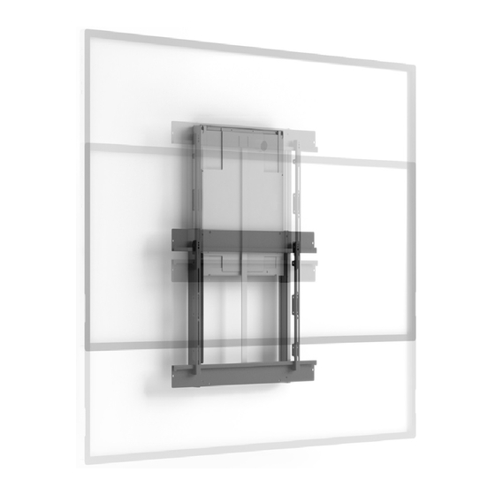
user manuAl
ez-lift SERIES
EZ1/ML145
Consists of:
EZ1/MB16/152
EZ1/MA1
Displays up to 39-83 lbs (18-38 kg)
VESA Mounting: 200 x 200 – 800 x 670
EZ1/ML209
Consists of:
EZ1/MB16/209
EZ1/MA1
Displays up to 135-197 lbs (61-90 kg)
VESA Mounting: 200 x 200 - 800 x 670
EZ1/ML095
Consists of:
EZ1/MB16/095
EZ1/MA5
Displays up to 41.4-85 lbs (18-38 kg)
VESA Mounting: 200 x 100 - 800 x 440
Salamander Interactive Wall Mounts
Mount Body
VESA Bracket
Mount Body
VESA Bracket
Mount Body
VESA Bracket
interactive
wall mounts
501-518 [04.21]
page 1 of 10
Advertisement

Related Manuals for Salamander Designs EZ Series


Summary of Contents for Salamander Designs EZ Series
- Page 1 user manuAl ez-lift SERIES interactive wall mounts EZ1/ML145 Consists of: Mount Body EZ1/MB16/152 VESA Bracket EZ1/MA1 Displays up to 39-83 lbs (18-38 kg) VESA Mounting: 200 x 200 – 800 x 670 EZ1/ML209 Consists of: Mount Body EZ1/MB16/209 VESA Bracket EZ1/MA1 Displays up to 135-197 lbs (61-90 kg) VESA Mounting: 200 x 200 - 800 x 670...
- Page 2 PARTS - EZ1/ML145 / EZ1/ML209 / EZ1/ML095 ML095 M4 x 12mm (10x) M4 x 12mm (10x) M6 x 12mm (10x) M6 x 12mm (10x) M8 x 10mm (10x) M8 x 10mm (10x) M8 x 12mm (10x) M8 x 12mm (10x) Salamander Interactive Wall Mounts 501-518 [04.21] page 2 of 10...
-
Page 3: General Warning
How to use this manual Read manual carefully before you install the mount Carry out the actions fully and in the given sequence The mount guarantee is voided if the product is not correctly installed or modified in any way Warning symbols used Sharp edges Wear glove Physical load D Two people required... - Page 4 Installation of EZ1/MB16/152 Mount Body Prepare Mounting Site The EZ-Lift was designed to be installed on a 16” on center 2” x 4” wood stud, or metal studs, using high-quality hollow wall anchor installed in the center of the stud or a solid concrete wall. WARNING: INSTALLING THE MOUNT IN UNDERRATED OR DAMAGED CONCRETE CAN LEAD TO SERIOUS INJURY OR DAMAGE TO PRODUCT! When installing into concrete only install the mount in a solid concrete wall made of 2500 PSI (17.3 MPa) or stronger concrete. Never install the mount into cracked, chipped or flaking concrete. WARNING: IMPROPER INSTALLATION CAN LEAD TO MOUNT FALLING CAUSING SERIOUS PERSONAL INJURY OR DAMAGE TO EQUIPMENT! It is the installers responsibility to make sure the structure to which the EZ-Lift is being installed is capable of supporting three times the combined weight of the EZ-Lift and all...
- Page 5 Determine mounting height See below for recommended mounting height for 55” Display. Other displays can be calculated by adding half the height difference to the top and half the height difference to the bottom of the example shown Mounting Bracket Hole Position 31.5” 84” [2134] 79.5” [2020] 16” Adjustable Range [406] 41.25” Approx. Lowest Screen Position [1048] Mounting bracket level to wall Unpack the EZ-Lift Take the wall bracket out (A) of the box. Note the slotted/slanted holes for level wall mounting. LOCK SCREW HOLE 11.8" 16” Salamander Interactive Wall Mounts 501-518 [04.21] page 5 of 10...
- Page 6 Make sure screws are unlocked Lift the mount onto bracket ools needed Salamander Interactive Wall Mounts 501-518 [04.21] page 6 of 10...
- Page 7 Lock mount with screws Level vertically with feet at the bottom Salamander Interactive Wall Mounts 501-518 [04.21] page 7 of 10...
- Page 8 Insert plastic cover Salamander Interactive Wall Mounts 501-518 [04.21] page 8 of 10...
- Page 9 Attach brackets to mount and display M4 x 12mm (10x) or M6 x 12mm (10x) or M8 x 12mm (10x) M4 x 12mm (10x) or M6 x 12mm (10x) or M8 x 12mm (10x) M8 x 10mm (4x) M8 x 10mm (4x) Hang display onto horizontal bracket and level Salamander Interactive Wall Mounts 501-518 [04.21]...
- Page 10 Lock display with safety lock screws from the bottom Vesa Bracket EZ1/MA1 4x M8 Max 10 mm Set balance Balancing: Springs are always fully tightened for safety. Use a drill driver and 1/2” (13 mm) socket, ATTACH THE SIDE COVERS TO THE MOUNT WALL COVER rotate counter clockwise (loosen) evenly. Do three seconds left and three seconds right until the mount BALANCEBOX®400 USING THE VESA is evenly balanced to support display weightlessly. BRACKET INSTALLATION POINTS AS SHOWN 1/2”...
Need help?
Do you have a question about the EZ Series and is the answer not in the manual?
Questions and answers