Table of Contents
Advertisement
Available languages
Available languages
Quick Links
We appreciate the trust and confidence you have placed in Hampton Bay through the purchase of this ceiling fan. We strive to continually create
quality products designed to enhance your home. Visit us online to see our full line of products available for your home improvement needs.
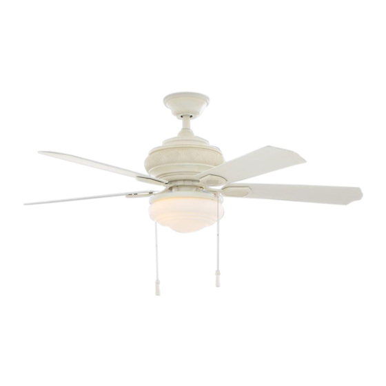
USE AND CARE GUIDE
PORTSMOUTH 52-INCH CEILING FAN
Questions, problems, missing parts? Before returning to the store,
call Hampton Bay Customer Service
8 a.m. - 6 p.m., EST, Monday-Friday.
1-855-HD-HAMPTON
HAMPTONBAY.COM
To view an instructional video on how to install this product:
1. Go to www.homedepot.com and enter either the Item or Model number, found in the top
right corner of the cover of this instruction manual, in the search eld.
2. Click on your product from the list of search results and click on the video link in the
"Product Overview" section.
Thank you for choosing Hampton Bay!
THANK YOU
Item #xxx xxx, xxx xxx
Model #51355, 51356
UL Model #52-PM
Advertisement
Chapters
Table of Contents

Related Manuals for HAMPTON BAY PORTSMOUTH 51355


Summary of Contents for HAMPTON BAY PORTSMOUTH 51355
- Page 1 THANK YOU We appreciate the trust and confidence you have placed in Hampton Bay through the purchase of this ceiling fan. We strive to continually create quality products designed to enhance your home. Visit us online to see our full line of products available for your home improvement needs.
-
Page 2: Table Of Contents
Table of Contents Table of Contents ..............2 Assembly ................7 Safety Information ............... 2 Operation ................12 Warranty ................3 Care and Cleaning ............. 13 Pre-Installation ..............3 Troubleshooting ..............13 Installation ................6 Safety Information All wiring must be in accordance with the National Electrical WARNING: To reduce the risk of personal injury, do Code ANSI/NFPA 70-1999 and local electrical codes. -
Page 3: Warranty
A certain amount of “wobble” is normal and should not be considered a defect. Servicing performed by unauthorized persons shall render the warranty invalid. There is no other express warranty. Hampton Bay hereby disclaims any and all warranties, including but not limited to those of merchantability and fitness for a particular purpose to the extent permitted by law. - Page 4 Pre-Installation (continued) HARDWARE INCLUDED NOTE: Hardware not shown to actual size. Part Description Quantity Part Description Quantity Blade attachment screws Close-to-ceiling mount hardware (rubber gasket) Wire connecting nut Pull chain Hanger pin Locking pin Extra blade bracket screw with lockwasher...
- Page 5 Pre-Installation (continued) PACKAGE CONTENTS Part Description Quantity Part Description Quantity Slide-on mounting bracket Decorative motor collar cover (inside canopy) Blade Ball/downrod assembly Blade bracket Canopy with canopy ring attached Glass shade Fan-motor assembly LED bulb, 9.5-Watt maximum Light kit fitter assembly IMPORTANT: This product and/or components are governed by one or more of the following U.S.
-
Page 6: Installation
Installation MOUNTING OPTIONS WARNING: To reduce the risk of fire, electric shock or NOTE: You may need a longer downrod to maintain personal injury, mount to outlet box marked “acceptable proper blade clearance when installing on a steep, sloped for fan support of 35lbs. (15.9 Kg) or less” and use ceiling. - Page 7 Assembly - Standard Ceiling Mount Preparing for standard mounting Routing the wires □ □ Remove the canopy ring (JJ) from the canopy (C) by turning the Route the wires exiting the top of the fan motor (D) into the ring counter-clockwise until it unlocks. decorative motor collar cover (F) and through the canopy □...
- Page 8 Assembly - Close-To-Ceiling Mount Preparing for close-to-ceiling Routing the wires mounting □ Remove three of the six screws and lockwashers (LL) (every □ Remove the canopy ring (JJ) from the canopy (C) by turning the other one) securing the motor collar (M) to the top of the fan ring counter-clockwise until it unlocks.
-
Page 9: Assembly
Assembly - Hanging the fan (continued) Hanging the fan Wrapping the extra wire WARNING: The hook is only to balance the fan while attaching NOTE: Follow this step ONLY if you did not cut the extra length off wiring. Failure to hang the fan according to these instructions from the wires coming from the ceiling fan to the receiver. - Page 10 Assembly - Hanging the Fan (continued) Making the electrical connections Outlet box in the ceilling MM WARNING: Each wire nut supplied with this fan is designed to accept up to one 12-gauge house wire and two wires from the Green or bare wire fan.
- Page 11 Assembly - Attaching the Fan Blades Fastening the blade assemblies to Attaching the fan blades the motor □ Fasten the blade assembly to the fan motor assembly (D) by IMPORTANT: Remove the rubber stopper on the black plate below the motor in order to attach the blade assembly to inserting the alignment post into the slot on the bottom of the the motor.
-
Page 12: Operation
Assembly - Attaching the Light Kit (continued) Installing the bulbs and glass shade □ With the power off, install two bulbs (J) (Max. 9.5W, included) by twisting them into the light bulb sockets. □ Place the glass shade (I) into the light kit fitter assembly (E), aligning the three flat areas on the top flange of the glass shade (I) with the three raised dimples in the light kit fitter assembly (E). -
Page 13: Care And Cleaning
Care and Cleaning WARNING: Make sure the power is off before cleaning your fan. □ Because of the fan’s natural movement, some connections may become loose. Check the support connections, brackets, and blade attachments twice a year. Make sure they are secure. It is not necessary to remove the fan from the ceiling. □... - Page 14 Questions, problems, missing parts? Before returning to the store, call Hampton Bay Customer Service 8 a.m. - 6 p.m., EST, Monday-Friday 1-855-HD-HAMPTON HAMPTONBAY.COM Retain this manual for future use.
- Page 15 GRACIAS POR TU COMPRA Apreciamos la confianza que has depositado en Hampton Bay al comprar este ventilador de techo. Nos esforzamos para continuamente crear productos de calidad diseñados para tu hogar. Visítanos por Internet para ver nuestra línea completa de productos disponibles para las necesidades de mejoras de tu hogar.
- Page 16 Tabla de Contenido Tabla de Contenido ............. 2 Ensamblaje ................7 Información de Seguridad ..........2 Funcionamiento ..............12 Garantía ................3 Mantenimiento y Limpieza..........13 Pre-Instalación..............3 Solución de Problemas ............. 13 Instalación ................6 Información de Seguridad Todo el cableado debe cumplir con el Código Nacional de ADVERTENCIA: Para reducir el riesgo de lesiones, no Electricidad ANSI/NFPA 70-1999 y con los códigos locales de dobles los soportes de las aspas (también llamados...
-
Page 17: Garantía
Es normal cierta “oscilación” y no debe ser considerado como un defecto. Cualquier servicio técnico conducido por personas no autorizadas anulará la garantía. No hay ninguna otra garantía expresa. Mediante la presente Hampton Bay se exime de cualquier garantía, incluyendo pero sin limitarse a aquellas de comercialización e idoneidad para un fin particular, de acuerdo a lo contemplado por la ley. - Page 18 Preinstalación (continuación) HERRAJES INCLUIDOS NOTA: No se muestra el tamaño real de los herrajes. Pieza Descripción Cantidad Pieza Descripción Cantidad Tornillos para el montaje de aspas Herrajes para montaje “cerca del techo” (junta de goma) Tuerca para conectar cables Pasador de soporte Interruptor de cadena Pasador de cierre Tornillo adicional para soporte de aspas...
- Page 19 Preinstalación (continuación) CONTENIDO DEL PAQUETE Pieza Descripción Cantidad Pieza Descripción Cantidad Soporte de montaje deslizante Cubierta decorativa del collarín del motor (dentro de la cubierta) Aspa Ensamblaje de tubo bajante/bola Soporte de aspa Cubierta con aro incorporado Pantalla de vidrio Ensamblaje del motor del ventilador Bombilla LED, máximo de 9.5 W Ensamblaje del soporte del kit de luces...
-
Page 20: Instalación
Instalación OPCIONES DE MONTAJE NOTA: Tal vez necesites un tubo bajante más largo para ADVERTENCIA: Para reducir el riesgo de incendio, mantener la altura mínima adecuada de las aspas, al descarga eléctrica o lesiones personales, monta el instalar el ventilador en un techo inclinado. El ángulo ventilador sobre una caja eléctrica marcada como máximo permitido es de 30º... - Page 21 Ensamblaje – Montaje de Techo Estándar Preparación para el montaje Disposición de los cables estándar □ □ Inserta los cables que salen por la parte superior del motor Retira el aro (JJ) de la cubierta (C), girándolo a la izquierda del ventilador (D) en la cubierta decorativa del collarín del hasta dejarlo suelto.
- Page 22 Ensamblaje – Montaje "Cerca del Techo" Preparación para el montaje Disposición de los cables cerca del techo □ □ Retira el aro (JJ) de la cubierta (C), girándolo a la izquierda Retira tres de los seis tornillos y arandelas de seguridad (LL) hasta dejarlo suelto.
-
Page 23: Ensamblaje
Ensamblaje – Cómo Colgar el Ventilador (continuación) Cómo colgar el ventilador Cómo enrollar el cable sobrante ADVERTENCIA: El gancho usado es sólo para sostener el NOTA: Sigue estos pasos SOLO si no cortaste el cable sobrante ventilador mientras se conectan los cables. Si no se cuelga del ventilador de techo. - Page 24 Ensamblaje – Cómo Colgar el Ventilador (continuación) Cómo hacer las conexiones eléctricas Montaje cerca del tech (MM) ADVERTENCIA: Cada cable no suministrado con este ventilador está diseñado para aceptar hasta un circuito eléctrico de casa de calibre 12 y dos cables del ventilador. Si tienes un cableado Verde o pelado superior a calibre 12 o más de un cable para conectar al ventilador, consulta a un electricista para el tamaño adecuado de...
- Page 25 Ensamblaje – Cómo Unir las Aspas del Ventilador Cómo ajustar los ensamblajes Cómo unir las aspas del ventilador de las aspas al motor □ IMPORTANTE: Quita el tope de goma de la placa negra bajo Ajusta el ensamblaje del aspa al ensamblaje del motor del el motor para instalar el ensamblaje de las aspas en el motor.
-
Page 26: Funcionamiento
Ensamblaje - Cómo Instalar el Kit de Luces (continuación) Cómo instalar las bombillas y la pantalla de vidrio □ Con la electricidad apagada, instala dos bombillas (J) (de 9.5 W máximo, incluidas) enroscándolas en los portabombillas. □ Coloca la pantalla de vidrio (I) en el ensamblaje del soporte del kit de luces (E), alineando las tres áreas planas en el reborde superior de la pantalla de vidrio (I) con las tres muescas salientes del ensamblaje del soporte del kit de luces (E). -
Page 27: Mantenimiento Y Limpieza
Mantenimiento y Limpieza ADVERTENCIA: Asegúrate de que la corriente esté apagada antes de limpiar el ventilador. □ Debido al movimiento natural del ventilador, algunas conexiones pueden aflojarse. Revisa las conexiones de soporte, soportes y accesorios de aspas dos veces al año. Verifica que estén seguros. No es necesario desmontar el ventilador del techo. □... - Page 28 ¿Preguntas, problemas o piezas faltantes? Antes de regresar a la tienda, llama al Servicio al Cliente de Hampton Bay de lunes a viernes entre 8 a.m. y 6 p.m., (hora del Este de EE. UU.) 1-855-HD-HAMPTON HAMPTONBAY.COM Conserva este manual para referencias futuras.
Need help?
Do you have a question about the PORTSMOUTH 51355 and is the answer not in the manual?
Questions and answers