Table of Contents
Advertisement
Advertisement
Table of Contents

Subscribe to Our Youtube Channel
Related Manuals for Ismart AMCE220NV3


Summary of Contents for Ismart AMCE220NV3
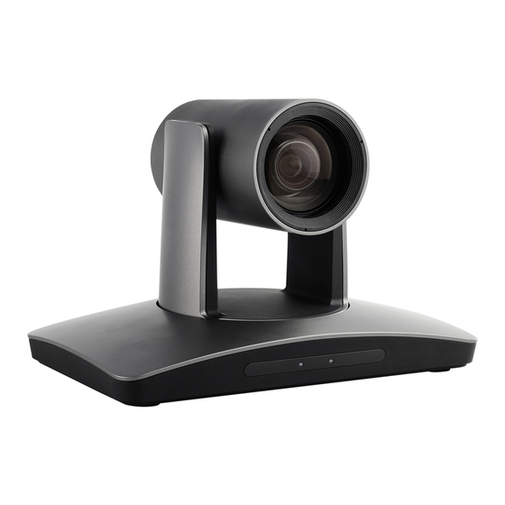
- Page 1 IP HD PTZ Color Video Camera User Manual V1.0...
- Page 3 SAFETY NOTICE-IMPORTANT!!! The following important notes must be followed carefully to run the camera and respective accessories in total safety. The camera and relative accessories are called video system in this section. Before installing the camera, please read this manual carefully. Please follow installation instructions indicated in this manual during installation.
- Page 4 Do not move the camera head manually. In doing so would result in malfunction of the camera. Do not hold the camera head when carrying the video camera. This camera is for indoor use only. It is not designed for outdoor use. ...
-
Page 5: Table Of Contents
CONTENTS ABOUT THE PRODUCT -------------------------------------------------------- 1 -------------------------------------------------------------------------------- 1 FEATURES ------------------------------------------------------------ 1 & LIST OF PARTS ACCESSORIES ---------------------------------------------------------------- 2 & MAIN PARTS INTERFACES ------------------------------------------------------------------ 4 SWITCHES SETTINGS --------------------------------------------------------------------- 5 REMOTE CONTROLLER INSTALLATION ---------------------------------------------------------------- 7 ------------------------------------------------------------ 7 DESKTOP MOUNT INSTALLATION ---------------------------------------------------------------- 7 WALL MOUNT INSTALLATION ) ---------------------------------------------------- 7 WALL BRACKET SUPPLIED SEPARATELY... - Page 6 TROUBLESHOOTING -------------------------------------------------------- 38...
-
Page 7: About The Product
List Of Parts & Accessories ABOUT THE PRODUCT When you open the box, check all accessories according to the packing list. Features Camera (1) 1/2.8 inch CMOS sensor, 2.14 megapixel; H.265, H.264 video compression; 3G-SDI, DVI output; ... -
Page 8: Main Parts & Interfaces
5 TF Card Slot Main Parts & Interfaces 6 USB 7 RJ45 (Network) Camera 8 HDMI Video Output Front View 9 3G-SDI 10 Audio 11 RS-232IN/IR 12 RS-232OUT/RS-485 13 Power(DC12V) 1 Camera Module 2 IR Sensor RS-232IN/IR Pin Definition 3 Power Indicator Number Definition 4 Communication Indicator... - Page 9 RS-232OUT/RS-485 Pin Definition Number Definition 485+ 485- Bottom View 14 DIP Switch Set camera address, protocol, baud rate, video format and mounting type. 15 Mounting Hole 1/4”inch screw thread for fixing camera. 16 Locating Hole To define installation direction of camera.
-
Page 10: Dip Switches Settings
DIP Switches Settings DIP No. OFF OFF VISCA Before installing and operating the camera, PELCO- D Protocol set the camera address, baud rate and video PELCO- P Reserved output format etc through DIP switches. The DIP No. camera has two 8-digit DIP switches: SW1 OFF OFF 2400 and SW2 as below:... -
Page 11: Remote Controller
1 HOME Remote Controller Press HOME button, camera moves to initial position. 2 Camera Selection Button Used to switch among 4 cameras, press 1-4 number buttons to control cameras with 1-4 addresses respectively. For example, press button 1 to control the camera with address 3 Focus Press “AUTO”... - Page 12 Used to input numbers, for example, preset In Menu status: get into relative menu number. option after it has been selected. 8 Cancel To cancel numbers input 16 Direction / Menu Operation In None-menu status, press these four 9 Power buttons to pan left/right and tilt up/down.
-
Page 13: Installation
INSTALLATION Note Take effective measures to avoid The camera has 3 installation types: desktop, camera from dropping. Do not grab the camera head when ceiling, wall mount installations. carrying. Do not rotate the camera head with hand. It may cause malfunction to the camera. -
Page 14: Ceiling Mount Installation
Use inch screws to fix the camera on the Fix the mounting plate onto the ceiling or bracket, fix the limit screw according to cement roof with 4 screws which should actual requirement, and make sure the be prepared by you. camera is tightly fixed onto the bracket before your hands leave the camera. -
Page 15: Connections
CONNECTIONS Note If preset 0 has been saved, after powered on, camera moves to preset 0 automatically; if preset 0 has not been saved, after powered on, camera moves to Home position, where both pan and tilt angle is zero and zooming time is 1x. -
Page 16: Menu Settings
MENU SETTINGS Menu Configuration <VIDEO> SHARPNESS 0, 1, 2, 3, 4, 5, 6, 7, 8, 9, 10, 11, 12, 13, 14, 15 Refer to 0, 1, 2, 3, 4, 5, 6, 7, 8, 9, 10, 11, 12, 13, 14 BRIGHTNESS Page 15 0, 1, 2, 3, 4, 5, 6, 7, 8, 9, 10, 11, 12, 13, 14 CONTRAST... - Page 17 <EXPOSURE> MODE FULL AUTO Refer to Page MANUAL GAIN 0, +2, +4, +6, +8, +10, +12, +14, +16, +18, +20, +22, +24, +26, +28,+30 SPEED 1/30, 1/60, 1/90, 1/100, 1/125, 1/180, 1/250, 1/350, 1/500, 1/725, 1/1000,1/1500, 1/2000, 1/3000, 1/4000, 1/6000, 1/10000 IRIS F14, F11, F9.6, F8,...
- Page 18 <COLOR> WB MODE AUTO, ATW, ONE PUSH, INDOOR, OUTDOOR, MANUAL, Refer to Page SODIUM LAMP, FLUO LAMP SATURATION 0, 1, 2, 3, 4, 5, 6, 7, 8, 9, 10, 11, 12, 13, 14 0, 1, 2, 3, 4, 5, 6, 7, 8, 9, 10, 11, 12, 13, 14 <PAN TILT ZOOM>...
- Page 19 <STATUS> ADDRESS Refer to Page PROTOCOL VISCA BAUD RATE 9600 IR ADDRESS VIDEO FORMAT 1080P25 MOUNT MODE STAND FIRMWARE VER 1.0.06 <RESTORE DEFAULTS> Refer to Page18...
-
Page 20: Menu Explanation
Submenus Menu Explanation From main menu, navigate to select Main Menu <EXPOSURE> menu, click IRIS to enter. <EXPOSURE>Set menu. Main MenuCall Preset #95 to enter menu. ❸ ❶ ❶ <MENU> <EXPOSURE> ❷ VIDEO MODE FULL AUTO EXPOSURE EX-COMP COLOR LEVEL ❷... -
Page 21: Video
Video Exposure VIDEO menu is used to change video value. EXPOSURE menu is used to adjust exposure value. <VIDEO> SHARPNESS <EXPOSURE> BRIGHTNESS MODE FULL AUTO CONTRAST EXP-COMP GAMMA MODE LEVEL 2DNR LEVEL 3DNR LEVEL ANTI-FLICKER WIDE DYNAMIC SELECT BACK SELECT BACK Available Options: MODE:... -
Page 22: Color
1/1500, 1/2000, 1/3000, 1/4000, 1/6000, COLOR 1/10000. COLOR menu is used to adjust color related IRIS PRI: Gain and shutter speed value are values. Available options: adjusted automatically according to working < COLOR> environment; Iris value is adjustable WB MODE MANUAL manually. -
Page 23: Pan/Tilt/Zoom
Pan/Tilt/Zoom System PAN/TILT/ZOOM is used to change <SYSTEM> ADDRESS pan/tilt/zoom value, available options: PROTOCOL VISCA BAUD RATE 9600 IR ADDRESS <PAN TILT ZOOM> VIDEO FORMAT 1080P25 PAN/TILT SPEED MOUNT MODE STAND D-ZOOM LIMIT RS485 PORT HALF-DUPLEX-1 PTZ TRIG AF LANGUAGE ENGLISH RATIO SPEED POWER UP ACTION... -
Page 24: Status
STATUS List of Special Preset Commands < STATUS> ADDRESS Preset No. Function PROTOCOL VISCA BAUD RATE 9600 Get into menu IR ADDRESS VIDEO FORMAT 1080P25 Delete all presets MOUNT MODE STAND FIRMWARE VER V3.1.02 Reboot the PTZ BACK Video format: 1920X1080P50 Video format: 1920X1080P25 Display information (address, protocol, baud Video format: 1920X1080I50... -
Page 25: Network Connection
Network Connection Connect the camera to network with an Ethernet cable, power on the camera. LAN Connection Please refer to the above diagram, user1 and user 2 are in the same router, they are considered as in the same LAN, connect the camera to the same LAN as where the PC is, and refer to below instructions as how to use the application software, then the camera can be found and connected from the online device list. - Page 26 Please refer to the above diagram, user and the camera are in different routers, they are considered as in a WAN; in this condition, application software iSmartCMS can not search and find the camera automatically. User can still connect after below conditions are satisfied: (1) Set camera’s IP address as static IP address (2) Router of the LAN where camera is connected supports Port Mapping.
- Page 27 10320, so mapping of camera 2 with (IP 115.200.31.100 + port 10320) is established. In the "Managed Device" of the client software iSmart CMS, click "+ Add", enter the IP address 115.200.31.100 and port 10200 and other information, then the camera 1 can be accessed and...
-
Page 28: Client Software Instruction
Client Software Instruction Search and list the camera Install and open the client software in PC, enter the main interface: If the camera and PC are in the same LAN, click “Start Search”, then searching starts and all online devices will be listed, as the picture shown below: To modify the device IP address, input the IP address, mask, gateway in the “Modify Network”... -
Page 29: Remote Configuration
To control and preview a camera, first choose the device, modify its IP address as the IP address of the same LAN, then click “Add to Client” as the picture shown below. Please check that all IP addresses are in the same LAN. Remote Configuration Choose the camera in the device list, click “Remote Configuration”... - Page 30 Upgrade Click “Upgrade” menu to enter the main interface, as the picture shown above. Click … to search and load the updating firmware, then click “Upgrade” to start upgrading. Do not power off the camera during upgrading. After upgrading is completed, camera will reboot.
- Page 31 Network Connect with: please choose from Static IP or dynamic IP address; IP address: input IP address for the camera; Mask: input mask address for the camera; Gateway: input gateway IP address; DNS 1: server-prior, input DNS address for the device; ...
- Page 32 Streaming Stream type: set the parameters of main stream, sub stream, third stream, fourth stream. Resolution: set among 4K(3840*2160), 1080P(1920*1080), 720P(1280*720), D1&QVGA(320*240), choose resolutions based on actual requirements and capability of device. The higher the resolution is, the better network requirements will be needed. ...
- Page 33 RTMP In RTMP1 and RTMP2, main stream, sub stream, third stream, fourth stream can be chosen to stream.
- Page 34 Control ● Password setting: when a password is required, the camera can be accessed only after a correct password is input. Reboot: reboot the camera.
- Page 35 Transparent Transmission Enable / Disable: enable / disable transparent transmission; Protocol: choose TCP or UDP protocols; Camera as: choose Client or Server; IP: when the camera is set as client, the IP address of the transmitted camera is needed. When the camera is set as server, the IP address can be left as black;...
- Page 36 Preview Click “Main View” to get into camera control and preview part as below. This interface includes three main parts: Device List, Device Control, Video Preview Device: It displays all online cameras added to “Device Management”.
- Page 37 Device Control: get control of the selected camera (camera name in blue). Video Preview: double click the camera in the list, main camera stream will be displayed in the preview window; or right click the selected camera from the left column to get its main or substream video.
-
Page 39: Annex 1 Technical Specifications
ANNEX 1 TECHNICAL SPECIFICATIONS Items Value Image Sensor 1/2.8" CMOS, 2.14 megapixel Focal Lens f=4.7~94.0mm f=3.9mm-46.8mm Iris F1.6 – F3.5 F1.6-F2.8 Optical Zoom Digital Zoom Horizontal Viewing Angle 59.5°-2.9° 72.5°-6.3° Focus System Auto, Manual, PTZ Trigger, One Push Trigger Exposure Control Auto, Manual, Shutter Priority, Iris Priority, Smart Min. - Page 40 IR Throughout Output 1 channel IR throughout output General Protocols VISCA (support daisy chain) / PELCO-P / PELCO-D Address 0~63 Power DC12V Power Consumption <20W Operating Temperature 0°C~+40°C Storage Temperature -20°C~+60°C Dimensions (W×H×D) 243mm×145mm×163mm Weight 1.2KG Body color grey...
-
Page 41: Annex 2 Size And Dimension
ANNEX 2 SIZE AND DIMENSION Front Rear Side Bottom... -
Page 42: Annex 3 Sw1 Definition
ANNEX 3 SW1 DEFINITION DIP No. Address... - Page 43 DIP No. Reserved Reserved Reserved DIP No. Ceiling Mounting Type Stand...
- Page 44 TROUBLESHOOTING Problem Possible Cause Solution Power supply failure Check power supply No action or image Power adapter damaged Replace power adapter after powered on Power cable connection got loosen Check & reconnect Power cable is too long Use a shorter cable No self-testing after powered on, or with Power adapter damaged...
- Page 45 The user manual is only for a reference, if there are any changes or differences, please ask for the latest version from your supplier CA/YF-AMCE200NV3-ZD-016 Y06020705021...
Need help?
Do you have a question about the AMCE220NV3 and is the answer not in the manual?
Questions and answers