
Subscribe to Our Youtube Channel
Related Manuals for fortessa FTDEV1 Series


Summary of Contents for fortessa FTDEV1 Series
- Page 1 2 WIRE SYSTEM FTDEV1 Series USER MANUAL FTDEV1 FTDEV2P • Please read this manual carefully to ensure safe and correct operation. • Keep this manual well for future reference.
-
Page 3: Table Of Contents
CONTENTS PARTS AND FUNCTIONS ..................1 Part Names......................1 Mounting ......................... 1 External Motion Detection ..................2 SETUP INSTRUCTIONS ..................3 Functions Setting Up ....................3 Setting Door Station Address ................. 4 Setting Door Station Calling Mode ................. 4 Setting Unlock Mode ....................6 Setting Unlock Time.................... -
Page 4: Parts And Functions
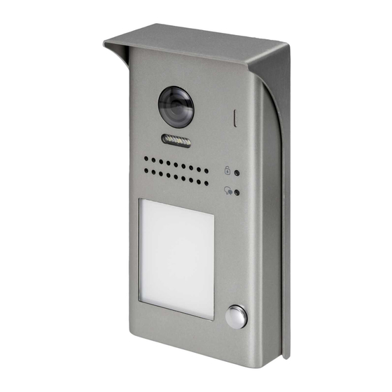
PARTS AND FUNCTIONS Part Names [11] [10] [12] [13] [1] Microphone [6] Front panel [10] Rain shield [2] UNLOCK indicator [7] Speaker [11] Mounting bracket [3] CALL indicator [8] Night view LED [12] Connection [4] Call button [9] Camera lens [13] Front Panel Screw [5] Nameplate Mounting... -
Page 5: External Motion Detection
PARTS AND FUNCTIONS Terminal description Lock Control Jumper PIR Motion Detector Terminal * (compatible monitor required) P L S + L 1 L 2 Terminal Connections Lock Control Jumper: To select the lock type. Motion Detector Terminals: To connect external PIR motion detector. * (compatible monitor required) Terminal Connections: To connect the bus line and the electronic locks. -
Page 6: Setup Instructions
SETUP INSTRUCTIONS Functions Set Up This section explains the settings of each function, please refer to the following ta- ble: LED_UNLOCK To perform the function settings, remove LED_TALK the metal front panel. KEY_SET KEY_4 Each operation is indicated by the lighting LED_NAME KEY_3 up of the LED indicator on the unit, and by... -
Page 7: Setting Door Station Address
SETUP INSTRUCTIONS Setting Door Station Address A maximum of 4 door station can be addressed and configured. This can be modified either be- fore or after installation. 0 is default, to change the setting, please follow the steps: ID=0,1 door station ID=1,2 door station ID=2,3... - Page 8 SETUP INSTRUCTIONS Each call button will respond to different addresses when set in different calling mode. Refer to the followings for more informations. 1.Standard calling mode(Address range 01-04 by default) Call buttonA: call the monitor with address 01 by default. Call buttonB: call the monitor with address 02 by default.
-
Page 9: Setting Unlock Mode
SETUP INSTRUCTIONS Setting Unlock Mode There are 2 unlock modes, Normally open and Normally closed. Normally open is default, to change the setting: In standby mode, press Press KEY_1 button to set Press KEY_1 button again KEY_SET button three the unlock mode to to set the unlock mode to times. -
Page 10: Setting Nameplate Illumination Mode
SETUP INSTRUCTIONS Setting Nameplate Illumination Mode There are 3 illumination modes for nameplate indicator, Normally on, Normally off and Auto. Normally on is default, to change the setting, please follow the steps: Press KEY_3 button to set Press KEY_3 button again Press KEY_3 button again In standby mode, press KEY_SET button three... -
Page 11: Setting Ring-Back Tone
SETUP INSTRUCTIONS Setting Ring-back Tone If allow ring-back tone, press the call button to call monitor, a ring-back call tone can be heard from door station. There are 3 ring-back call tones, Ringing one time, Ringing continuously and No ring-back tone. -
Page 12: Wiring
WIRING Connecting Electric Lock Door Lock Controlled with Internal Power 1 2 3 1.Electronic lock, Power-on-to-unlock, (Failsecure) should be used. Jumper position on 2&3 2.The door lock output is limited to 12V, 250mA. PL S+ S- 3.The jumper should be placed on position 2 and 3 before connecting and applying power. -
Page 13: Connecting Basic One-To-One
WIRING Connecting Basic One-to-one ID=0 Code=1, DIP6=on 230VAC FTDEV1PSU BUS(IM) BUS(DS) L1 L2 PL S+ S- DIP Switches 1 2 3 4 5 6 • The door station work in Standard mode in this situation. Refer to Page 8 in detail. •... -
Page 14: Connecting Multi Monitors
WIRING Connecting Multiple Monitors Basic IN-OUT Wiring in Standard Mode • Other monitors are available. • Please set door station into group calling Code=1, DIP6=on mode if there are more than 4 monitors (Slave 3) operated with one push button, or apart- ment.(Refer to Page 8) •... - Page 15 WIRING Star Topology Wiring With FTDEV1VD in Standard Mode Code=1,DIP6=on Code=2,DIP6=on Impedance OFF ON switch Code=3,DIP6=on Code=4,DIP6=on 230VAC FTDEV1PSU8 BUS(IM) BUS(DS) ID=0 • Please refer to FTDEV1VD instructions for more details. -12-...
-
Page 16: Appendix
Excessive moisture may cause problems with the unit. • You must use the right power supply which is supplied by Fortessa. • The mains AC supply must be carried out by a skilled electrician who is familiar with the ap- propriate standards and technical requirements of the product taking in to consideration the latest building regulations. -
Page 17: Cables And Requirments
APPENDIX Cables and Requirments The maximum distance of the wiring is limited in the system. Using different cables may also affect the maximum distance which the system can reach. Basic IN-OUT Wiring Mode Cable and distance(unit:m) IM: Indoor Monitor Cable Usage ≤2 IM ≤16 IM Twisted cable 2x0.75mm... - Page 18 APPENDIX Star Topology Wiring Mode With FTDEV1VD FTDEV1VD FTDEV1PSU8 Cable and distance(unit:m) Cable Usage Twisted cable 2x0.75mm Twisted cable 2x1mm -15-...
- Page 19 Note -16-...
- Page 20 Due to our policy of continuous improvement we reserve the right to change specification with- out prior notice. Errors and omissions excepted. These instructions have been carefully checked prior to pub- lication. However, no responsibility can be accepted by Challenger Security Products for any misinterpretation of these instructions.
Need help?
Do you have a question about the FTDEV1 Series and is the answer not in the manual?
Questions and answers