Table of Contents
Advertisement
Quick Links
Advertisement
Table of Contents

Subscribe to Our Youtube Channel
Related Manuals for fortessa FTDEV1P


Summary of Contents for fortessa FTDEV1P
- Page 1 2 -Wire Intercom System FTDEV1P User Manual FTDEV1P FTDEV1P_Instructions _Rev02...
-
Page 2: Table Of Contents
CONTENTS 1.Parts and Functions..................... 1 2.Terminal Descriptions ..................1 3.Specifications ...................... 2 4.Mounting ......................2 4.1 Mounting Without Rainy Cover ..............2 4.2 Mounting With Rainy Cover ................3 4.3 Placing Name Label ..................3 4.4 Adjusting Camera Angle ................4 5.System Wiring and Connections ................. -
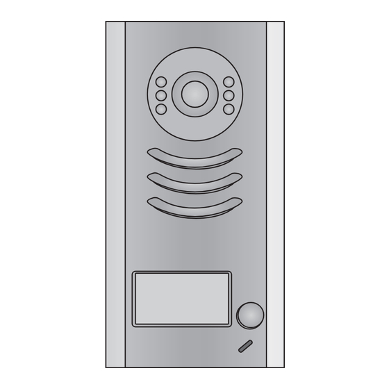
Page 3: Parts And Functions
1.Parts and Functions Camera Lens Night View LED Speaker Nameplate Call Button Microphone Rainy Cover 90 mm 23 mm 2.Terminal Descriptions 1 2 3 Lock Control Jumper Doorstation Code DIP MIC adjustment SPK adjustment Main Connect Port S 2 + S - P L S 1 + B U S... -
Page 4: Specifications
• To select the lock type: see 5.2.1 , 5.2.2 Lock Control Jumper: • Total 4 doorstations can be supported,see 6.1 Doorstation Code DIP: • To connect the bus line and the electronic locks. Main Connect Port: • BUS: Connect to the bus line, no polarity. •... -
Page 5: Mounting With Rainy Cover
4.2 Mounting With Rainy Cover 160-165cm 4.3 Placing Name Label Move the plastic cover away to open the transparent name label cover, insert a name paper, then put the plastic cover back to the panel. name label... -
Page 6: Adjusting Camera Angle
4.4 Adjusting Camera Angle use a screwdriver to loosen the screw and then adjust 5.System Wiring and Connections 5.1 Basic Connection monitor FTDEV1PSU monitor Fail Secure Lock L1 L2 PL S1+ S2+ S-... -
Page 7: Electric Lock Connection
5.2 Electric Lock Connection 5.2.1 Door Lock Controlled with Internal Power Note: Electronic lock of Power-on-to-unlock type should be used. The door lock is limited to 12V, and holding current must be less than 250mA. The door lock control is not timed from Exit Button(EB). Parameter of Monitor must be set to 0 (by default). -
Page 8: How To Setup The Unlock Parameter In Monitor
Then input the code 8021~8029 (8021 = 1 second, 8029 = 9 seconds) to change the unlock time. Note: 1.must connect FTDEV1P correctly before setting. 2.the parameter will be saved in FTDEV1P automatically,so you need only set on one monitor. refer to the corresponding user manual. -
Page 9: Multi Doorstations Connection
5.3 Multi Doorstations Connection monitors DBC4 A B C D 85~260VAC 4# Camera 3# Camera 2# Camera 1# Camera ID=11 ID=01 ID=10 ID=00 L1 L2 PL S1+ S2+ S- L1 L2 PL S1+ S2+ S- L1 L2 PL S1+ S2+ S- L1 L2 PL S1+ S2+ S-... -
Page 10: Multi Monitors Connection
5.4 Multi Monitors Connection 5.4.1 Basic IN-OUT Wiring Mode 3 4 5 6 3 4 5 6 3 4 5 6 3 4 5 6 Code=7, DIP-6=on Code=4, DIP-6=off Code=5, DIP-6=off Code=6, DIP-6=off monitor monitor monitor monitor 3 4 5 6 3 4 5 6 3 4 5 6 3 4 5 6... -
Page 11: With Dbc-4 Wiring Mode
5.4.2 With DBC-4 Wiring Mode monitor monitor 3 4 5 6 3 4 5 6 Code=14, DIP-6=on Code=15, DIP-6=on monitor monitor 3 4 5 6 3 4 5 6 Code=12, DIP-6=on Code=13, DIP-6=on monitor monitor 3 4 5 6 3 4 5 6 Code=2, DIP-6=on Code=3, DIP-6=on monitor... -
Page 12: Setup
6.Setup ON(1) OFF(0) 6.1 DIP Switches Settings of Doorstation installation. Bit state Descriptions ID = 1(01), set to the second Door Station. ID = 2(10), set to the third Door Station. ID = 3(11), set to the fourth Door Station. 6.2 DIP Switches Settings of Monitor There are 6 bit switches in total. - Page 13 Bit-1 to Bit-5 are used to User Code setting. The value is from 0 to 31, which have 32 different codes . Bit state User Code Bit state User Code Bit state User Code Code=0 Code=11 Code=22 3 4 5 3 4 5 3 4 5 Code=1...
-
Page 14: Notices
6.3 Notices Name Discription Usage Connect with multi doorstations or Power Combo Unit, 24V 0.75A FTDEV1PSU multi monitors(up to 2) DC outputs Connect with one doorstation and one Power Combo Unit, 26V 2A DC outputs monitor(up to 8 ) FTDEV1PSU8 -12-... -
Page 15: Cables Requirements
7.Cables Requirements The maximum distance of the wiring is limited in the DT system. Using different cables may also affect the maximum distance which the system can reach. The farest monitor monitor with two or four monitors monitor monitor DBC/DBC-4 When Monitor quantity <... - Page 16 ROHS FTDEV1P_Instructions _Rev02 FORTESSA distributed by CHALLENGER SECURITY PRODUCTS 10 Sandersons Way, Blackpool, FY4 4NB Tel :01253 791888 Fax:01253 791887 Email: enquiries.challenger@adivision.co.uk Website: www.challenger.co.uk...
Need help?
Do you have a question about the FTDEV1P and is the answer not in the manual?
Questions and answers