Woodland Mills HM130MAX Operator's Manual
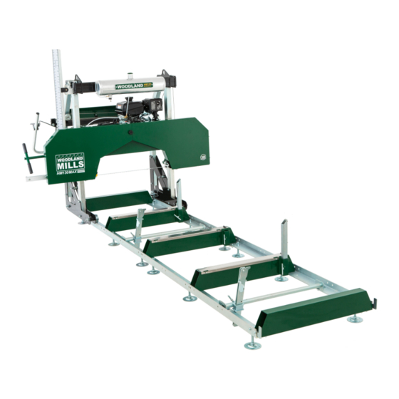
Portable sawmill
Hide thumbs
Also See for HM130MAX:
- Assembly instructions manual (20 pages) ,
- Operator's manual (96 pages) ,
- Operator's manual (80 pages)

Related Manuals for Woodland Mills HM130MAX


Summary of Contents for Woodland Mills HM130MAX
- Page 1 HM130MAX PORTABLE SAWMILL ™ 14 Horsepower Electric Start OPERATOR’S MANUAL HM130MAX ™ is a trademark of Woodland Mills, Inc.
-
Page 3: Table Of Contents
LEVELLING FEET ______________________________________________ LEVELLING THE TRACK ________________________________________ CARRIAGE STOPS _____________________________________________ LOG CLAMPS _________________________________________________ LOG SUPPORTS _______________________________________________ 4. SAWMILL HEAD ASSEMBLY __________________________________ FRONT POSTS _________________________________________________ CARRIAGE LEGS ______________________________________________ HEAD LOCK-DOWN PLATES ____________________________________ STANDING THE SAWHEAD UPRIGHT ____________________________ HM130MAX-MY2021-EN: Rev F Page 14-Jul-2021... - Page 4 ENGINE OIL ___________________________________________________ PRE START-UP CHECKLIST _______________________________________ SAWMILL SET-UP PROCEDURES __________________________________ DIRECTION OF CUT ___________________________________________ DRIVE BELT TENSION _________________________________________ BLADE TENSION ______________________________________________ TENSIONING METHODS ________________________________________ BELLEVILLE WASHER STACK ___________________________________ BLADE TRACKING ____________________________________________ TEST PROCEDURE _____________________________________________ HM130MAX-MY2021-EN: Rev F Page 14-Jul-2021...
- Page 5 BAND WHEEL HOUSING DOORS ________________________________ BAND WHEELS AND BELT TENSIONER ___________________________ ENGINE COMPONENTS ________________________________________ CARRIAGE ___________________________________________________ CARRIAGE LEG, WHEEL, AND SWEEPER ________________________ LIFT MECHANISM ____________________________________________ THROTTLE HANDLE __________________________________________ CABLES, TUBING & LABELS ___________________________________ PARTS LIST ___________________________________________________ NOTES _______________________________________________________ HM130MAX-MY2021-EN: Rev F Page 14-Jul-2021...
-
Page 6: Introduction
For technical questions and replacement parts, please contact Woodland Mills Inc. INTENDED USE Woodland Mills wood sawmills are designed for acreage owners to aid in the milling of natural, untreated wood with the mill firmly supported on the ground. Materials that are processed may contain chemicals or by-products that could corrode the machine or damage it, resulting in safety concerns. -
Page 7: Safety, Warning & Information Symbols
Instructions do not pertain to electric sawmills. Instructions can be skipped and ignored when working with an electric sawmill. **Look for symbols in the upper-right corner of the page throughout the manual.** HM130MAX-MY2021-EN: Rev F Page 14-Jul-2021... -
Page 8: Safety Guidelines
NOTE: All Federal and State laws and any regulation having jurisdiction covering the safety requirements for use of the machine take precedence over the statements in this manual. Users of this machine must adhere to such regulations. HM130MAX-MY2021-EN: Rev F Page 14-Jul-2021... -
Page 9: Work Area
• ALWAYS check the fuel lines and the fuel tank for leaks and cracks before starting the engine. Do not run the machine if fuel leaks are present or the fuel lines are loose. • ALWAYS avoid contact with hot fuel, oil, and exhaust fumes. HM130MAX-MY2021-EN: Rev F Page 14-Jul-2021... -
Page 10: Personal Safety
Always shut the engine off, remove the ignition key, and turn the engine off before carrying out any of the aforementioned procedures. Consult your engine manual for safe shutdown procedures to prevent accidental ignition. HM130MAX-MY2021-EN: Rev F Page 14-Jul-2021... -
Page 11: Tool Use And Care
Always deal with coiled blades, including those packaged in boxes, with the utmost care. Never use the equipment to cut anything other than lumber or for any purpose other than • cutting lumber as described in this manual. HM130MAX-MY2021-EN: Rev F Page 14-Jul-2021... -
Page 12: Equipment Operation
To avoid death or serious injury, do not cut lumber containing embedded foreign objects such as nails, metal fragments, etc. WARNING! The operator and any assistants must stay clear of the front and back of the blade whenever the engine is on. HM130MAX-MY2021-EN: Rev F Page 14-Jul-2021... -
Page 13: Maintenance
Lifting Cables — Before, during, and after operation, regularly inspect the cables for any • wear or kinks. Ensure that the cables are in perfect condition. Oil the coiled part of the cable often to prevent premature wear. Replace with new cables as necessary. HM130MAX-MY2021-EN: Rev F Page 14-Jul-2021... -
Page 14: Technical Specifications
HM130MAX ™ Operator’s Manual TECHNICAL SPECIFICATIONS The HM130MAX sawmill comes with a 14 horsepower electric-start engine. Item HM130MAX Specification Gasoline Engine 14 hp Kohler Command Pro Max Log Diameter 30 in [762 mm] Max Board Width 30 in [762 mm] Max Board Thickness 7 in [178 mm] Blade Size 1-¼... -
Page 15: Overall Dimensions
HM130MAX ™ Operator’s Manual OVERALL DIMENSIONS HM130MAX-MY2021-EN: Rev F Page 14-Jul-2021... -
Page 16: Assembly
During several of the assembly steps, more than one socket or wrench of the same size may be required to assemble the hardware. A socket or box wrench in combination with an adjustable wrench can be utilized if multiple same size tools are in limited supply. HM130MAX-MY2021-EN: Rev F Page 14-Jul-2021... -
Page 17: Unpacking
Carefully rotate the sawhead down onto the cardboard and support blocks and slide it out of the crate as shown below. The two long track boxes can now be removed and the crate discarded. HM130MAX-MY2021-EN: Rev F Page 14-Jul-2021... -
Page 18: Track
Levelling Foot Carriage Stop Base * Centre bunk incorporates four (4) mounting holes at each end If a Woodland Mills sawmill trailer was purchased with this sawmill, skip this track assembly section and follow the track assembly instructions in those manuals. -
Page 19: Rails & Centre Bunk
4-6 in [100-150 mm] off the ground for ease of assembly.. Build track up off the ground on large timbers or blocks for ease of assembly, preferably 4-6 in [100-150 mm] tall HM130MAX-MY2021-EN: Rev F Page 14-Jul-2021... - Page 20 Snug the bolts enough so that minor adjustments to the track width can be made once all the bunks are assembled to the rails. 37 in [940 mm] M10 X 35 mm Flanged Hex Bolts Reinforcement plate positioned under rails M10 Flanged Lock Nuts HM130MAX-MY2021-EN: Rev F Page 14-Jul-2021...
-
Page 21: Mid & End Bunks
& mid bunk locations. Snug the hardware in the same manner as the centre bunk. Ensure bunks are oriented so that the log support sleeves are all on the same side M10 X 25 mm Flanged Hex Bolts M10 Flanged Lock Nuts HM130MAX-MY2021-EN: Rev F Page 14-Jul-2021... -
Page 22: Squaring The Track And Setting The Width
(16) M10 X 35 mm flanged hex bolts and their nuts working from the centre out towards the ends as shown with the black arrows above. Double-check the track width and squareness after tightening. Readjust if necessary. END BUNKS SQUARE TO RAILS HM130MAX-MY2021-EN: Rev F Page 14-Jul-2021... -
Page 23: Levelling Feet
Fully tighten the bottom nut and position the second nut roughly 3-½—4 in [90—100 mm] from the bottom of the foot base. Ensure the position of the second nut is the same for all twelve (12) levelling foot assemblies. HM130MAX-MY2021-EN: Rev F Page 14-Jul-2021... - Page 24 With the feet loosely assembled to the rails, remove the timber/block supports so the full weight of the track is resting on middle nuts of the levelling feet. HM130MAX-MY2021-EN: Rev F Page 14-Jul-2021...
-
Page 25: Levelling The Track
Turn the middle nut on each foot to fine-tune the level. Once level, secure each foot to the rail by tightening the M16 top nut. Secure each foot by tightening the top nut to the rail Adjust the level of each foot by turning the middle nut HM130MAX-MY2021-EN: Rev F Page 14-Jul-2021... -
Page 26: Carriage Stops
M10 X 25 mm Flanged Hex Bolt Leave the carriage stops off one end if the sawmill head will be manually lifted onto the track. See section PLACING THE HEAD ON THE TRACK (METHOD 2). HM130MAX-MY2021-EN: Rev F Page 14-Jul-2021... -
Page 27: Log Clamps
HM130MAX ™ Operator’s Manual LOG CLAMPS Assemble the log clamps using the components and hardware listed in the table below. The HM130MAX comes with two (2) log clamp assemblies. M10 X 25 mm Log Clamp Flanged Hex Shaft/Bracket Bolt Weldment... - Page 28 Depending on how many track sections are being used, select a log clamp position that will secure the log firmly against a minimum of two log supports. M10 X 25 mm Flanged Hex Bolt M10 Flanged Lock Nut HM130MAX-MY2021-EN: Rev F Page 14-Jul-2021...
- Page 29 Ensure the log clamp tilts towards the log when clamping. If it tilts away from the log, remove the log clamp from the receiver, loosen the T-bolt, reverse the receiver on the shaft by rotating it 180°, and retighten the T-bolt. Insert the log clamp back into the receiver. HM130MAX-MY2021-EN: Rev F Page 14-Jul-2021...
-
Page 30: Log Supports
M10 Hex Nut M10 X 25 mm Flanged Hex Bolt The log supports can be installed into any of the sleeves on the centre or mid bunks. HM130MAX-MY2021-EN: Rev F Page 14-Jul-2021... - Page 31 Once the log support is square with the top of the bunk, tighten both jam nuts. Secure the log support with the T-bolt. Repeat the process for the centre and mid bunks as necessary. HM130MAX-MY2021-EN: Rev F Page 14-Jul-2021...
-
Page 32: Sawmill Head Assembly
There are wedge-shaped caps on the bottom of each post to help aid the assembly of the posts through the nylon post sleeve bushings. Note hole orientation. Wider spaced holes at bottom. Wedge cap on bottom of each post HM130MAX-MY2021-EN: Rev F Page 14-Jul-2021... - Page 33 HM130MAX ™ Operator’s Manual Remove the wedge-shaped caps from the bottom of both posts. They are only required for front post assembly. HM130MAX-MY2021-EN: Rev F Page 14-Jul-2021...
-
Page 34: Carriage Legs
Snug these four (4) M12 bolts just enough so that the plates are flush to the posts but do not fully tighten them. Push the posts all the way up until the carriage leg plates contact the post sleeves. HM130MAX-MY2021-EN: Rev F Page 14-Jul-2021... -
Page 35: Head Lock-Down Plates
HEAD LOCK-DOWN PLATES Woodland Mills sawmill trailer owners only If a Woodland Mills sawmill trailer was purchased with this sawmill, the head lock-down plates can be loosely installed prior to standing the sawhead upright. The lock-down plates come with the sawmill trailers and are not included with the sawmill. -
Page 36: Standing The Sawhead Upright
With the help of another person, stand the sawhead upright by rotating it around the rounded profiles at the front of the carriage legs. Do not set the sawhead on the track until instructed to do so later in the assembly process. HM130MAX-MY2021-EN: Rev F Page 14-Jul-2021... -
Page 37: Rear Posts
Using the hardware listed below, attach the rear posts between the carriage leg plates using one (1) M12 X 80 mm bolt, lock nut, and two (2) flat washers per post. M12 X 80 mm Hex Bolt M12 Lock Nut Rear Post M12 Flat Washer HM130MAX-MY2021-EN: Rev F Page 14-Jul-2021... -
Page 38: Cross Beam
5 mm spacer in the open slot. Use an M12 flat washer under every bolt head and lock nut. Finally, install two (2) M12 X 80 mm bolts at the top of each carriage leg. Do not fully tighten these bolts at this time. HM130MAX-MY2021-EN: Rev F Page 14-Jul-2021... - Page 39 ™ Operator’s Manual M12 X 110 mm @ Pulleys Log Scale Mounting Bracket M12 X 90 mm 6 Places M12 X 35 mm 5 mm Spacer M12 X 80 mm Assemble these bolts last HM130MAX-MY2021-EN: Rev F Page 14-Jul-2021...
-
Page 40: Lubrication Tank
M8 X 16 mm Lubrication Hex Bolt Tank M8 Lock Nut Assemble the lubrication tank to the cross beam with four (4) M8 X 16 mm bolts and lock nuts. Ensure the bolts point inward. HM130MAX-MY2021-EN: Rev F Page 14-Jul-2021... -
Page 41: Battery Connections
If only the recoil start will be utilized (no battery), remove the positive cable (red) from the engine solenoid shown here. If the electric start will be utilized, remove terminal cover and continue to next step. Positive Cable (Red) HM130MAX-MY2021-EN: Rev F Page 14-Jul-2021... - Page 42 Once the connections are made, set the battery box lid on top ensuring the battery cables route down and out the openings in the side. Use the included strap to secure the top and bottom halves of the battery box. HM130MAX-MY2021-EN: Rev F Page 14-Jul-2021...
-
Page 43: Dashboard & Hour Meter
(1) M12 X 130 mm bolt (with pulley and spacer) as illustrated on the next page. Use an M12 flat washer under every bolt head and lock nut. Do not fully tighten these bolts at this time. HM130MAX-MY2021-EN: Rev F Page... - Page 44 This will activate the meter to start measuring the vibration of the machine, recording the hours of use on the engine. Cut wire loop on hour meter after sawmill is assembled HM130MAX-MY2021-EN: Rev F Page 14-Jul-2021...
-
Page 45: Lift Mechanism
(1) M12 X 110 mm bolt. Use an M12 flat washer under each bolt head and lock nut. Fasten the centre tab to the inside of the dashboard using an M10 X 25 mm bolt and nut. Do not fully tighten these bolts at this time. HM130MAX-MY2021-EN: Rev F Page 14-Jul-2021... - Page 46 HM130MAX ™ Operator’s Manual M12 X 150 mm Bolt 20.5 mm Spacer 5 mm Spacer M10 X 25 mm Bolt M12 X 110 mm Bolt HM130MAX-MY2021-EN: Rev F Page 14-Jul-2021...
-
Page 47: Lift Cable Routing
(2) M10 flange nuts at the other end. The cable lengths are unique to each side so do not swap them. Route lift cable A (right side) as shown below. Route Lift Cable A around lower pulleys Eyebolt end Dashboard removed for clarity HM130MAX-MY2021-EN: Rev F Page 14-Jul-2021... - Page 48 flange nut that was removed, sandwiching the bracket between both flange nuts. Repeat the process for the other lift cable. Do not fully tighten this hardware. Lift Cable B Lift Cable A Components removed for clarity HM130MAX-MY2021-EN: Rev F Page 14-Jul-2021...
-
Page 49: Log Scale
Hex Bolt Magnetic M6 Lock Nut Scale [White] M6 Flat Magnetic Washer Scale [Yellow] Scale Support Spacer Plate Scale Indicator Arrow Bracket [Rear] Scale Indicator Arrow Bracket [Front] Scale Indicator Arrow M8 X 25 mm Knob HM130MAX-MY2021-EN: Rev F Page 14-Jul-2021... - Page 50 2 in + blade kerf. side after drying. Blade Kerf The graduations on the white magnetic scale make allowances for the blade kerf. On the yellow magnetic scale the kerf is not accounted for in the measurements. HM130MAX-MY2021-EN: Rev F Page 14-Jul-2021...
- Page 51 Adjust position of mounting bracket to prevent binding Store the other magnetic scale on the front side of the scale support when not in use. Store unused magnetic scale on front side of scale support HM130MAX-MY2021-EN: Rev F Page 14-Jul-2021...
-
Page 52: Push Handle
For ground-mount setups, For sawmill trailer setups, assemble the push handle assemble the push handle pointing upwards pointing downwards Ground-Mount Push Handle and Throttle Sawmill Trailer Push Handle and Handle Recommended Position Throttle Handle Recommended Position HM130MAX-MY2021-EN: Rev F Page 14-Jul-2021... - Page 53 (2) M10 X 70 mm bolts and M10 flanged lock nuts as shown below. Fully tighten these bolts. The push handle can be adjusted/rotated forwards or backwards to suit the ergonomics of the operator in either ground-mount or sawmill trailer configurations. HM130MAX-MY2021-EN: Rev F Page 14-Jul-2021...
-
Page 54: Throttle Handle And Cable
There are two (2) M6 hex bolts, two (2) lock nuts, and six (6) flat washers. Assemble the throttle handle to the uppermost pair of holes in the push handle. Note the location of the six (6) flat washers Shorter Bolt [50 mm] Longer Bolt [55 mm] HM130MAX-MY2021-EN: Rev F Page 14-Jul-2021... - Page 55 This will take the slack out of the cable. Actuator Tab Barrel Clamp and Screw Adjustment Screw Unsheathed Cable Idle Position The assembled throttle handle and routed cable should now match the image below. HM130MAX-MY2021-EN: Rev F Page 14-Jul-2021...
-
Page 56: Band Wheel Door Latches
Use two (2) M4 X 10 mm flat head screws per latch. Assemble the latches to the pre-installed spacers on the bottom of the band wheel housing. On each band wheel door, install the hook- shaped catch using two (2) M4 X 10 mm flat head screws with lock nuts. HM130MAX-MY2021-EN: Rev F Page 14-Jul-2021... -
Page 57: Adjustable Blade Guide Handle
M12 flat washer and the handle, and thread it into the aluminum blade guide arm. Then secure it on the back side of the arm using the other M12 flat washer and M12 lock nut. HM130MAX-MY2021-EN: Rev F Page 14-Jul-2021... -
Page 58: Lubrication Tubing
fitting on the guide block holder shaft. Route tube Route tube from through tab valve on tank Connect both tubes to barbed fittings on auto-lube valve Connect tubing to either barbed fitting HM130MAX-MY2021-EN: Rev F Page 14-Jul-2021... -
Page 59: Tighten Carriage Wheel Bolts
HM130MAX ™ Operator’s Manual TIGHTEN CARRIAGE WHEEL BOLTS Tighten the four (4) M20 X 120 mm bolts that fasten the carriage wheels to the carriage side plates. HM130MAX-MY2021-EN: Rev F Page 14-Jul-2021... -
Page 60: Placing The Head On The Track
1000 lb. [450 kg]. Attach the lifting strap/chain to the lifting eyes, raise the head up, and rest it on the track so that the grooves in the carriage wheels fit around the track rails. Two people are recommended for this procedure. Lifting Eyes HM130MAX-MY2021-EN: Rev F Page 14-Jul-2021... -
Page 61: Method 2
Afterwards, tighten all of the saw head bolts, post and cross beam hardware. HM130MAX-MY2021-EN: Rev F Page 14-Jul-2021... -
Page 62: Rolling The Sawmill Head Assembly
Make the necessary adjustments to the track and roll the head assembly again. Repeat the track adjustments until the head rolls freely. HM130MAX-MY2021-EN: Rev F Page 14-Jul-2021... -
Page 63: Raising & Lowering The Sawhead
When the desired cut depth is reached, releasing the handle will lock the arm into one of the slots in the indexing plate. Push handle Crank handle in inward while locked/default turning crank arm position Indexing Plate HM130MAX-MY2021-EN: Rev F Page 14-Jul-2021... -
Page 64: Levelling The Sawmill Head Assembly
flange nuts securely against lift mechanism brackets. Turn right-side flange nut clockwise to raise the side of the sawmill head, counter- clockwise to lower it. Lift Cable B Loosen left-side flange nut Lift Cable A Loosen left-side flange nut HM130MAX-MY2021-EN: Rev F Page 14-Jul-2021... -
Page 65: Adjust The Post Sleeve Bushings
With the wear pads flush with the posts, tighten all the hex bolts and spray the posts with a water resistant silicone lubricant such as “WD-40 Water Resistant Silicone Spray” or “3-in- One Silicone Spray Lubricant.” HM130MAX-MY2021-EN: Rev F Page 14-Jul-2021... -
Page 66: Greasing Threads
flat spots on the rubber belts. These flat spots will cause the mill to vibrate excessively during subsequent uses.** Add grease to all T-bolt threads on the sawmill track: three (3) on the bunks and one (1) on the log clamp assembly. HM130MAX-MY2021-EN: Rev F Page 14-Jul-2021... -
Page 67: Engine Oil
When changing the engine oil, follow the instructions on the next page. HM130MAX-MY2021-EN: Rev F Page 14-Jul-2021... - Page 68 M12 sealing washer should be replaced after each oil change Repeat the process in reverse to re-install the drain plug. Remember to hold the brass extension stationary with a second wrench when tightening the plug. HM130MAX-MY2021-EN: Rev F Page 14-Jul-2021...
-
Page 69: Pre Start-Up Checklist
1 minute. Always mill at full throttle. 8. After the first hour of use, inspect the drive belt tension and adjust if required. Refer to the operator’s manual for detailed tensioning instructions. HM130MAX-MY2021-EN: Rev F Page 14-Jul-2021... -
Page 70: Sawmill Set-Up Procedures
(backwards) due to manufacturing processes and they must be flipped prior to installation. **Please follow the instructions throughout the SAWMILL SET-UP PROCEDURES section. Failure to do so may result in poor sawing performance, damage or injury.** HM130MAX-MY2021-EN: Rev F Page 14-Jul-2021... -
Page 71: Drive Belt Tension
Then loosen the M8 bolt (2A) in the curved slot—its nut (2B) is secured in place by an anti-rotation device and does not require a second wrench or socket. **Only loosen the bolts approx. one turn—do not remove them.** HM130MAX-MY2021-EN: Rev F Page 14-Jul-2021... - Page 72 (#1), then tighten the upper bolt in the curved slot in a clockwise direction using a 13 mm socket (#2). Re-check the belt tension to ensure a maximum of ¼ in [6 mm] deflection and then tighten the M16 bolt and lock nut when the deflection is correct (#3). HM130MAX-MY2021-EN: Rev F Page 14-Jul-2021...
-
Page 73: Blade Tension
Operator’s Manual BLADE TENSION Woodland Mills sawmills use an ACME threaded rod for blade tensioning mounted within an assembled stack of Belleville washers for blade cushioning. This combined assembly allows for predictable and repeatable tensioning throughout all temperature ranges with minimal wear and maintenance. -
Page 74: Tensioning Methods
If the bearing is proud of the tube under recommended tension, remove shim washers. • If the bearing is beyond the tube under Not Flush (Proud) recommended tension, add shim washers. • Retune approx. every 100 hours. HM130MAX-MY2021-EN: Rev F Page 14-Jul-2021... -
Page 75: Belleville Washer Stack
five (5) groups of four washers (4)—each containing two (2) opposing nested pairs —with a single nested pair at each end. There may also be up to six (6) shims installed if the flush bearing method is being utilized. HM130MAX-MY2021-EN: Rev F Page 14-Jul-2021... -
Page 76: Blade Tracking
Tuning the blade tracking is a process of testing and adjusting—re-testing and adjusting— re-testing and adjusting. The number of cycles is determined by how far off the tracking was at the start of the process. ‣ Please see the following pages for testing and adjustment procedures. HM130MAX-MY2021-EN: Rev F Page 14-Jul-2021... -
Page 77: Test Procedure
first, rerun this test procedure, then adjust the other side if needed. ‣ Because ¼ turn adjustment increments are recommended, it is common to run this test a few times between multiple adjustments before correct tracking is achieved. Follower-Side Drive-Side HM130MAX-MY2021-EN: Rev F Page 14-Jul-2021... -
Page 78: Follower-Side Adjustment
3. Repeat the Test Procedure to see if further adjustment is needed. 4. Repeat the follower-side adjustment steps and test procedure as many times as necessary until the blade is tracking properly. HM130MAX-MY2021-EN: Rev F Page 14-Jul-2021... -
Page 79: Drive-Side Adjustment
6. Repeat the Test Procedure to see if further adjustment is needed. 7. Repeat the drive-side adjustment steps and test procedure as many times as necessary until the blade is tracking properly. HM130MAX-MY2021-EN: Rev F Page 14-Jul-2021... -
Page 80: Tracking Run-In
fifteen (15) seconds, and then turn the engine off and wait for the blade to stop spinning. 6. Open the band wheel housing doors and confirm the tracking settings have held. 7. Bring the guides forward into place and set as per the following section, BLADE GUIDE ADJUSTMENT. HM130MAX-MY2021-EN: Rev F Page 14-Jul-2021... -
Page 81: Blade Guide Adjustment
Position it so that there is a thick paper-sized gap (.040 in or 1 mm) between the bearing and the back of blade. Re-tighten the bolt against the flat on the shaft to secure the assembly into position. .040 in / 1 mm Thick Paper HM130MAX-MY2021-EN: Rev F Page 14-Jul-2021... - Page 82 Using a feeler gauge or thick piece of paper (.020 in / 0.5 mm), place it between the blade and both guide blocks and then tighten the set screws. .020 in [0.5 mm] gap .040 in [1 mm] gap HM130MAX-MY2021-EN: Rev F Page 14-Jul-2021...
-
Page 83: Adjustable Blade Guide Calibration
Turning it counter-clockwise will tighten the arm movement; turning it clockwise will loosen the movement. Ensure the lock nut behind the V-roller is also tightened while adjusting the eccentric V-roller Eccentric V-Roller Counter-clockwise: tighten arm movement Clockwise: loosen arm movement **Some components removed for clarity.** HM130MAX-MY2021-EN: Rev F Page 14-Jul-2021... -
Page 84: Ball Plunger Adjustment
Once the guide arm is Adjust the ball plunger so moving well, tighten the that only the ball is in ball plunger jam nut. contact with the arm. HM130MAX-MY2021-EN: Rev F Page 14-Jul-2021... -
Page 85: Carriage & Guide Arm Adjustment
See previous section, BLADE GUIDE ADJUSTMENT, for more information. ABG will rotate about this button head screw Once the ABG is properly adjusted, fully tighten the four (4) button head screws on the carriage. HM130MAX-MY2021-EN: Rev F Page 14-Jul-2021... -
Page 86: Sawmill Maintenance
Install a new blade following the reverse order of steps and then set the proper blade tension. The tracking should not have to be adjusted after changing blades. See section, ADJUSTING THE FOLLOWER SIDE TRACKING, for more information. HM130MAX-MY2021-EN: Rev F Page 14-Jul-2021... -
Page 87: Replacing Belts
BX57 Follower Belt BX80 Drive Belt First, remove the blade following the procedure outlined in section, CHANGING THE BLADE. Release blade tension Remove blade Rotate blade stopper up Remove blade guard until parallel with blade HM130MAX-MY2021-EN: Rev F Page 14-Jul-2021... - Page 88 The belt can now easily be removed by hand and a new belt installed. Tension the belt following the same procedure as outlined in section, DRIVE BELT TENSION. HM130MAX-MY2021-EN: Rev F Page 14-Jul-2021...
- Page 89 **Note that blade tracking should not have changed after replacing the belts. The RapidChange blade system maintains the band wheel pitch angle while the blade is removed. Refer to section, BLADE TRACKING, for more information.** HM130MAX-MY2021-EN: Rev F Page 14-Jul-2021...
-
Page 90: Troubleshooting
8. Run the sawmill without lubrication for 30 minutes in not adjusted properly. order to dress new belts sufficiently before adding water for lubrication. Refer to page 67 (#3). 9. Call Woodland Mills Technical Support. 1. Too many blade 1. Replace blade. Refer to page 84. sharpenings. - Page 91 1. Level the sawhead by adjusting the lift cable ends Sawhead difficult 2. Front posts not lubricated. under the lift mechanism. Refer to page 62. to raise or lower 2. Spray front posts with water resistant silicone lubricant. HM130MAX-MY2021-EN: Rev F Page 14-Jul-2021...
-
Page 92: Replacement Parts Ordering
HDW part number, record the description (e.g. HEX BOLT, M10 X 1.5, 25 mm LG, FULL) from the “Description” column. Contact Woodland Mills through the website (or via phone/email) and provide the list of part numbers and/or hardware descriptions, including quantities for each item. -
Page 93: Exploded Assembly Views
HM130MAX ™ Operator’s Manual EXPLODED ASSEMBLY VIEWS TRACK HM130MAX-MY2021-EN: Rev F Page 14-Jul-2021... -
Page 94: Sawhead
HM130MAX ™ Operator’s Manual SAWHEAD HM130MAX-MY2021-EN: Rev F Page 14-Jul-2021... -
Page 95: Back Beam
HM130MAX ™ Operator’s Manual BACK BEAM HM130MAX-MY2021-EN: Rev F Page 14-Jul-2021... -
Page 96: Guide Block Holders
HM130MAX ™ Operator’s Manual GUIDE BLOCK HOLDERS HM130MAX-MY2021-EN: Rev F Page 14-Jul-2021... -
Page 97: Band Wheel Housing
HM130MAX ™ Operator’s Manual BAND WHEEL HOUSING HM130MAX-MY2021-EN: Rev F Page 14-Jul-2021... -
Page 98: Band Wheel Housing Doors
HM130MAX ™ Operator’s Manual BAND WHEEL HOUSING DOORS HM130MAX-MY2021-EN: Rev F Page 14-Jul-2021... -
Page 99: Band Wheels And Belt Tensioner
HM130MAX ™ Operator’s Manual BAND WHEELS AND BELT TENSIONER HM130MAX-MY2021-EN: Rev F Page 14-Jul-2021... -
Page 100: Engine Components
HM130MAX ™ Operator’s Manual ENGINE COMPONENTS HM130MAX-MY2021-EN: Rev F Page 14-Jul-2021... -
Page 101: Carriage
HM130MAX ™ Operator’s Manual CARRIAGE HM130MAX-MY2021-EN: Rev F Page 14-Jul-2021... -
Page 102: Carriage Leg, Wheel, And Sweeper
HM130MAX ™ Operator’s Manual CARRIAGE LEG, WHEEL, AND SWEEPER HM130MAX-MY2021-EN: Rev F Page 14-Jul-2021... -
Page 103: Lift Mechanism
HM130MAX ™ Operator’s Manual LIFT MECHANISM HM130MAX-MY2021-EN: Rev F Page 14-Jul-2021... -
Page 104: Throttle Handle
HM130MAX ™ Operator’s Manual THROTTLE HANDLE 225 2X 252 2X 225 2X 252 2X HM130MAX-MY2021-EN: Rev F Page 14-Jul-2021... -
Page 105: Cables, Tubing & Labels
HM130MAX ™ Operator’s Manual CABLES, TUBING & LABELS HM130MAX-MY2021-EN: Rev F Page 14-Jul-2021... -
Page 106: Parts List
0002665 BLADE GUARD, ADJUSTABLE BLADE GUIDE 0002667 KNOB, MULTI-LOBE, 38 mm OD, M8 X 1.25, 12 mm LG 0002022 GUIDE BLOCK HOLDER BRACKET, LEFT 0001093 GUIDE BLOCK HOLDER 0001096 GUIDE BLOCK HOLDER SHAFT, BLADE STOPPER HM130MAX-MY2021-EN: Rev F Page 14-Jul-2021... - Page 107 BATTERY CABLE, POSITIVE (RED), 6 AWG, 12 in LG 0002929 SAW BLADE, 7/8 in PITCH, 181 TEETH, 1-1/4 WD X 158 LG X .042 in THK 0001416 FRONT POST, 50 X 80 mm, 1425 mm LG HM130MAX-MY2021-EN: Rev F Page 14-Jul-2021...
- Page 108 COMPRESSION SPRING, CLOSED GROUND ENDS, 0.720 in OD, 0.096 in DIA WIRE, 1.750 in 0004975 LG, 86 lb/in RATE 0002633 SELF-LOCKING CRANK HANDLE ARM 0004214 SPACER, 16.5 ID X 25 OD X 2 mm LG, NYLON 0003251 SPACER, 12 ID X 18 OD X 20.5 mm LG HM130MAX-MY2021-EN: Rev F Page 14-Jul-2021...
- Page 109 HEX BOLT, CLS 8.8, M10 X 1.5, 50 mm LG, FULL HEX BOLT, CLS 8.8, M12 X 1.75, 20 mm LG, FULL HEX BOLT, CLS 8.8, M12 X 1.75, 35 mm LG, FULL HEX BOLT, CLS 8.8, M12 X 1.75, 45 mm LG, FULL HM130MAX-MY2021-EN: Rev F Page 14-Jul-2021...
- Page 110 FLAT WASHER, M16 FLAT WASHER, M20 FENDER WASHER, M6, 18 mm OD FENDER WASHER, M8, 30 mm OD FENDER WASHER, M10, 30 mm OD FENDER WASHER, M10, 34 mm OD FENDER WASHER, M10, 35 mm OD HM130MAX-MY2021-EN: Rev F Page 14-Jul-2021...
- Page 111 LOCK NUT, CLS 8, M12 X 1.75 LOCK NUT, CLS 8, M16 X 2 LOCK NUT, CLS 8, M20 X 2.5 LOCK NUT, FLANGED, CLS 10, M10 X 1.5 SLOTTED NUT, ROUND, M14 X 1.5 HM130MAX-MY2021-EN: Rev F Page 14-Jul-2021...
-
Page 112: Notes
HM130MAX ™ Operator’s Manual NOTES HM130MAX-MY2021-EN: Rev F Page 14-Jul-2021... - Page 113 HM130MAX ™ Operator’s Manual HM130MAX-MY2021-EN: Rev F Page 14-Jul-2021...
- Page 114 HM130MAX ™ Operator’s Manual HM130MAX-MY2021-EN: Rev F Page 14-Jul-2021...
Need help?
Do you have a question about the HM130MAX and is the answer not in the manual?
Questions and answers
Need a water zert