Woodland Mills HM122 Operator's Manual
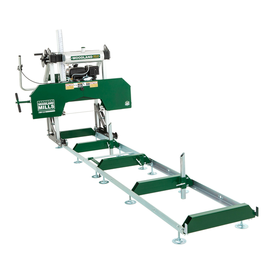
Portable sawmill
Hide thumbs
Also See for HM122:
- Operator's manual (92 pages) ,
- Owner's manual (52 pages) ,
- Assembly instructions manual (20 pages)
Table of Contents
Advertisement
Quick Links
Advertisement
Table of Contents

Related Manuals for Woodland Mills HM122


Summary of Contents for Woodland Mills HM122
- Page 1 HM122 PORTABLE SAWMILL 7 and 9.5 Horsepower Models OPERATOR’S MANUAL...
-
Page 3: Table Of Contents
HM122 Operator’s Manual TABLE OF CONTENTS TABLE OF CONTENTS _______________________________________ INTRODUCTION _____________________________________________ INTENDED USE _____________________________________________ SAFETY, WARNING & INFORMATION SYMBOLS __________________ SAFETY GUIDELINES ________________________________________ WORK AREA __________________________________________________ INTERNAL COMBUSTION ENGINE SAFETY _________________________ PERSONAL SAFETY ____________________________________________ TOOL USE AND CARE __________________________________________... - Page 4 HM122 Operator’s Manual STANDING THE SAWHEAD UPRIGHT ____________________________ REAR POSTS __________________________________________________ CROSS BEAM _________________________________________________ LIFT MECHANISM & LIFT CABLE ________________________________ LUBRICATION TANK & TUBING __________________________________ LOG SCALE ___________________________________________________ DASHBOARD __________________________________________________ HOUR METER _________________________________________________ PUSH HANDLE ________________________________________________ THROTTLE HANDLE AND CABLE...
- Page 5 HM122 Operator’s Manual BLADE GUIDE ADJUSTMENT ____________________________________ SAWMILL MAINTENANCE ____________________________________ CHANGING THE BLADE ________________________________________ REPLACING BELTS ____________________________________________ TROUBLESHOOTING _______________________________________ REPLACEMENT PARTS ORDERING ___________________________ EXPLODED ASSEMBLY VIEWS _______________________________ TRACK ______________________________________________________ SAWHEAD ___________________________________________________ BACK BEAM __________________________________________________ GUIDE BLOCK HOLDERS _______________________________________ BAND WHEEL HOUSING...
-
Page 6: Introduction
For technical questions and replacement parts, please contact Woodland Mills Inc. INTENDED USE Woodland Mills wood sawmills are designed for acreage owners to aid in the milling of natural, untreated wood with the mill firmly supported on the ground. Materials that are processed may contain chemicals or by-products that could corrode the machine or damage it, resulting in safety concerns. -
Page 7: Safety, Warning & Information Symbols
HM122 Operator’s Manual SAFETY, WARNING & INFORMATION SYMBOLS Throughout this operator’s manual there are safety, warning, and information symbols. Please heed and obey all warnings. Symbol Description Refer to instruction/operator’s manual Wear protective gloves Wear safety footwear Wear eye protection... -
Page 8: Safety Guidelines
HM122 Operator’s Manual SAFETY GUIDELINES **SAVE THESE INSTRUCTIONS** WARNING! Read and understand all instructions. Failure to follow all instructions listed below may result in electric shock, fire, and/or serious injury. WARNING! The warnings, cautions, and instructions discussed in this instruction manual cannot cover all possible conditions or situations that could occur. -
Page 9: Work Area
HM122 Operator’s Manual WORK AREA Keep work area clean, free of clutter and well lit. Cluttered and dark work areas can • cause accidents. Do not use your sawmill where there is a risk of causing a fire or an explosion; e.g. in •... -
Page 10: Personal Safety
HM122 Operator’s Manual PERSONAL SAFETY • Stay alert, watch what you are doing and use common sense when operating a power tool. Do not use a power tool when you are tired or under the influence of drugs, alcohol, or medication. -
Page 11: Tool Use And Care
HM122 Operator’s Manual TOOL USE AND CARE Always be sure the operator is familiar with proper safety precautions and operation • techniques before using machine. Never touch the engine or muffler while the engine is on or immediately after it has been •... -
Page 12: Equipment Operation
HM122 Operator’s Manual EQUIPMENT OPERATION Wear heavy-duty work gloves, ANSI-approved goggles behind a full face shield, steel-toed work boots, hearing protection, and a dust mask. Operate only with assistance. Cut-off branches from the lumber to be processed. Place the lumber to be cut on the track supports. -
Page 13: Maintenance
HM122 Operator’s Manual MAINTENANCE Proper and routine maintenance is critical to operator safety, achieving good milling results, and to prolong the life of your investment. Band Wheel Bearings — Inspect before use to ensure they are not worn. Bearings are •... -
Page 14: Technical Specifications
HM122 Operator’s Manual TECHNICAL SPECIFICATIONS The HM122 sawmill comes in two variants: the HM122-7 that utilizes a 7 horsepower engine and the HM122-9.5 with a 9.5 horsepower engine. Both versions are assembled and operated in the same manner. Pictures and graphics used in this manual display the HM122-9.5 sawmill but the instructions still apply to both. -
Page 15: Overall Dimensions
HM122 Operator’s Manual OVERALL DIMENSIONS HM122-MY2021-EN: Rev F Page 14-Jul-2021... -
Page 16: Assembly
HM122 Operator’s Manual ASSEMBLY 1. TOOLS REQUIRED Tool Specification Wrench/Socket 7 mm (2X) Wrench/Socket 10 mm (2X) Wrench/Socket 13 mm (2X) Wrench/Socket 14 mm (2X) Wrench/Socket 15 mm (2X) Wrench/Socket 16 mm (2X) Wrench/Socket 17 mm (2X) Wrench/Socket 18 mm (2X) -
Page 17: Unpacking
HM122 Operator’s Manual 2. UNPACKING Unpack the contents of the crate except for the sawhead and the two long boxes in the bottom that contain the sections of track. Unfasten the two (2) M8 bolts/nuts on the front of the crate using a socket/wrench. -
Page 18: Track
Mid Bunk M10 Flanged End Bunk Lock Nut Levelling Foot Base If a Woodland Mills sawmill trailer was purchased with this sawmill, skip this track assembly section and follow the track assembly instructions in those manuals. HM122-MY2021-EN: Rev F Page... -
Page 19: Rails & Mid (Centre) Bunk
HM122 Operator’s Manual RAILS & MID (CENTRE) BUNK Assemble one of the mid bunks over the joint between both pairs of track rails using the components and hardware listed in the table below. M10 X 30 mm Flanged Hex Track Rail... - Page 20 HM122 Operator’s Manual Next, assemble one of the mid bunks over the rail joints with a reinforcement plate under the rails on both the left and right sides. Use six (6) M10 X 30 mm flanged hex bolts and M10 flanged lock nuts per side.
-
Page 21: Mid & End Bunks
HM122 Operator’s Manual MID & END BUNKS Assemble the mid and end bunks in the locations shown using the components and hardware listed in the table below. M10 X 25 mm Flanged Hex Mid Bunk Bolt M10 Flanged End Bunk Lock Nut Use sixteen (16) M10 X 25 mm flanged hex bolts and M10 flanged lock nuts (4 per bunk) at all... -
Page 22: Squaring The Track And Setting The Width
HM122 Operator’s Manual SQUARING THE TRACK AND SETTING THE WIDTH The assembled track measures 26 in [660 mm] wide when measuring from the outside faces of the rails. With the bunk hardware connections only snug-tight, the rails can be moved in or out as needed until the proper width is achieved along the entire length of the track. -
Page 23: Levelling Feet
HM122 Operator’s Manual LEVELLING FEET Assemble the levelling feet using the components and hardware listed in the table below. M16 X 120 mm Levelling Foot Hex Bolt Base M16 Hex Nut Assemble twelve (12) sets of levelling feet, each one with a levelling foot base, an M16 X 120 mm hex bolt, and two (2) M16 hex nuts. - Page 24 HM122 Operator’s Manual Attach the twelve (12) levelling feet assemblies to the rails at the locations shown below. Assemble the levelling feet up through the bottom of the rails and thread an M16 hex nut onto each of the M16 X 120 mm hex bolts. Do not tighten the nut. Leave it loose enough so a noticeable gap exists between the nut and the rail to allow for track levelling in a later step.
-
Page 25: Levelling The Track
HM122 Operator’s Manual LEVELLING THE TRACK Working from the middle of the track out towards each end, check the rails for level lengthwise along the rails and widthwise across the rails. Work from the centre of the track out towards each end Turn the middle nut on each foot to fine-tune the level. -
Page 26: Carriage Stops
HM122 Operator’s Manual CARRIAGE STOPS Assemble the carriage stops to the inside face of the rails using the components and hardware listed in the table below. M10 X 25 mm Flanged Hex Carriage Stop Bolt M10 Flanged Lock Nut Use two (2) M10 X 25 mm flanged hex bolts and M10 flanged lock nuts to assemble each carriage stop to the insides of the track rails. -
Page 27: Log Clamp
HM122 Operator’s Manual LOG CLAMP Assemble the log clamps using the components and hardware listed in the table below. Log Clamp M8 X 20 mm Connecting Hex Bolt M8 Lock Nut Log Clamp Arm Log Clamp Grease the threads of the log clamp prior to threading it into the log clamp arm.. Orient the arm so that the bottom tube protrudes towards the side that the log clamp is being assembled. - Page 28 HM122 Operator’s Manual Attach the log clamp assembly to the rails as shown below using two (2) M8 X 20 mm hex bolts and M8 lock nuts. Note that there are multiple locations along the track where the log clamp can be bolted.
-
Page 29: Log Supports
HM122 Operator’s Manual LOG SUPPORTS Assemble the log supports to the centre and mid bunks using the components and hardware listed in the table below. M10 X 25 mm Bevelled Log Flanged Hex Support Bolt Key Stop Log M10 Hex Nut Support Assemble six (6) M10 X 25 mm flanged hex bolts and six (6) M10 hex jam nuts (2 each per... - Page 30 HM122 Operator’s Manual If the log support is not square (90°) to the top surface of the bunk when the T-bolt is tightened, the two (2) M10 X 25 mm flanged hex bolts can adjust the angle. 90° Check for squareness Loosen the T-bolt and push the log support into the corner of the bunk sleeve making sure neither bolt protrudes into the sleeve.
-
Page 31: Sawmill Head Assembly
HM122 Operator’s Manual 4. SAWMILL HEAD ASSEMBLY The sawmill head assembly is built in multiple steps. Follow the steps in the sub-sections below using the parts tables at the top of each sub-section to gather the necessary components and hardware for each step. - Page 32 HM122 Operator’s Manual Install the M6 X 16 mm hex bolt into the threaded hole near the top of the inside of M6 X 16 mm Bolt the left post as shown to the left. This acts as a stop for the sawhead so it cannot be...
-
Page 33: Carriage Legs
HM122 Operator’s Manual CARRIAGE LEGS The carriage leg sub-assemblies come loosely assembled from the factory. Final tightening of these bolts will be done in a later step. See the CARRIAGE LEG, WHEEL, AND SWEEPER exploded view for a more detailed part breakdown. -
Page 34: Head Lock-Down Plates
HEAD LOCK-DOWN PLATES Woodland Mills sawmill trailer owners only If a Woodland Mills sawmill trailer was purchased with this sawmill, the head lock-down plates can be loosely installed prior to standing the sawhead upright. The lock-down plates come with the sawmill trailers and are not included with the sawmill. -
Page 35: Standing The Sawhead Upright
HM122 Operator’s Manual STANDING THE SAWHEAD UPRIGHT With the help of another person, stand the sawhead upright by rotating it around the rounded profiles at the front of the carriage legs. Do not set the sawhead on the track until instructed to do so later in the assembly process. -
Page 36: Rear Posts
HM122 Operator’s Manual REAR POSTS Using the hardware listed below, attach the rear posts between the carriage leg plates using only one (1) M12 X 80 mm bolt, two (2) flat washers, and one (1) lock nut per post. M12 X 80 mm... -
Page 37: Cross Beam
HM122 Operator’s Manual CROSS BEAM With the hardware listed below, assemble the cross beam to the carriage posts. Cross Beam M12 X 90 mm and Pulley Hex Bolt Assembly Log Scale M12 X 80 mm Mounting Hex Bolt Bracket M12 X 30 mm Spacer ... - Page 38 HM122 Operator’s Manual With the help of a second person, slide the cross beam over the carriage posts. Use seven (7) M12 X 80 mm bolts and one (1) M12 X 90 mm bolt (@ log scale mounting bracket) to fasten it in place.
-
Page 39: Lift Mechanism & Lift Cable
HM122 Operator’s Manual LIFT MECHANISM & LIFT CABLE Assemble the winch assembly to the right-rear post using the hardware listed below. The wire rope lift cable, crank arm, and index plate come pre-assembled to the winch. Winch and M8 X 70 mm... - Page 40 HM122 Operator’s Manual Route the lift cable as shown in the steps below. [Engine removed from some views for clarity.] Cable crimp joint Lift cable comes pre- assembled to winch. Short cable end Long cable end Long cable routed...
- Page 41 HM122 Operator’s Manual Connect the shorter end of the lift cable to the bolt in front of the left-front post. Connect the longer end of the lift cable to the turnbuckle next to the front-right post by removing the upper clevis pin and locking ring. The turnbuckle will be adjusted later when the sawhead is levelled.
-
Page 42: Lubrication Tank & Tubing
HM122 Operator’s Manual LUBRICATION TANK & TUBING With the hardware listed below, assemble the lubrication tank to the front of the cross beam and route the plastic tubing. M8 X 16 mm Drip Nozzle Hex Bolt Lubricant M8 Lock Nut... - Page 43 HM122 Operator’s Manual The copper drip nozzle comes assembled to one of the pre-cut lengths of tubing. Remove the the copper drip nozzle from the tubing and assemble it into the follower-side guide block holder as shown below. Other sawmill components have been removed for clarity.
- Page 44 HM122 Operator’s Manual Route one length of tubing from the blue ring fitting on the tank to the vertical barbed fitting on the auto-lube valve. Route the other length of tubing from the horizontal barbed fitting on the auto-lube valve, down to the copper drip nozzle on the guide block holder shaft.
-
Page 45: Log Scale
HM122 Operator’s Manual LOG SCALE With the hardware listed below, assemble the log scale components. M6 X 15 mm Scale Support Hex Bolt Magnetic M6 Lock Nut Scale [White] M6 Flat Magnetic Washer Scale [Yellow] Scale Indicator Arrow Bracket [Rear]... - Page 46 HM122 Operator’s Manual Bolt the scale support—through the end with only two (2) slots—to the back beam with two (2) M6 X 15 mm bolts, flat washers, and lock nuts as shown below. Bolt scale support to back beam through end with only 2 slots Note: the sawmill comes with two (2) different magnetic scales: one yellow, one white.
- Page 47 HM122 Operator’s Manual Assemble the indicator arrow brackets and arrow to the log scale mounting bracket using the M8 threaded knob. Adjust the position of the mounting bracket forwards or backwards if the arrow locking plates bind on the log scale bracket as the sawhead is raised and lowered.
-
Page 48: Dashboard
HM122 Operator’s Manual DASHBOARD With the hardware listed below, assemble the dashboard to the rear carriage posts. M10 X 80 mm M10 Flat Hex Bolt Washer M10 X 75 mm Dashboard Hex Bolt M10 Lock Nut Assemble the dashboard to the rear carriage posts with four (4) M10 X 80 mm bolts through the upper holes and four (4) M10 X 75 mm bolts through the lower holes as shown. -
Page 49: Hour Meter
HM122 Operator’s Manual 20.32 13/16 HOUR METER 20.32 With the hardware listed below, assemble the hour meter to the dashboard. 13/16 M4 X 30 mm M4 Flat Pan Head Washer Screw M4 Lock Nut Hour Meter Assemble the hour meter to the right-side of the dashboard through the two (2) small holes. -
Page 50: Push Handle
HM122 Operator’s Manual PUSH HANDLE With the hardware listed below, assemble the push handle to the right rear carriage leg. M10 X 70 mm Flanged Hex Push Handle Bolt M10 Flanged Lock Nut The push handle is installed in an upward position when the sawmill is ground-mounted (below- left). - Page 51 HM122 Operator’s Manual When a desired push handle orientation has been decided upon, attach the push handle to the side of the post using two (2) M10 X 70 mm bolts and M10 flanged lock nuts as shown below. Fully tighten these bolts.
-
Page 52: Throttle Handle And Cable
HM122 Operator’s Manual THROTTLE HANDLE AND CABLE Use the hardware listed below to assemble the throttle handle to the push handle and route the throttle cable to the engine. M4 X 12 mm Phillips Pan Head Screw Throttle Handle Assembly... - Page 53 HM122 Operator’s Manual With the throttle lever in the idle position (fully open), route the cable around the front-right carriage post. Pass the cable through the thimble in the auto-lube bracket and pull the unsheathed portion of the cable through the hole in the actuator tab, then to the engine.
-
Page 54: Band Wheel Door Latches
HM122 Operator’s Manual BAND WHEEL DOOR LATCHES Using the hardware listed below, assemble the two (2) bottom band wheel door latches. M4 X 10 mm Phillips Flat Latch Head Screw M4 Lock Nut Use two (2) M4 X 10 mm flat head screws per latch. Assemble the latches to the pre-installed spacers on the bottom of the band wheel housing. -
Page 55: Tighten Carriage Wheel Bolts
HM122 Operator’s Manual TIGHTEN CARRIAGE WHEEL BOLTS Tighten the four (4) M20 X 120 mm bolts that fasten the carriage wheels to the carriage side plates. HM122-MY2021-EN: Rev F Page 14-Jul-2021... -
Page 56: Placing The Head On The Track
HM122 Operator’s Manual 5. PLACING THE HEAD ON THE TRACK At this point, most of the sawmill head bolts should only be hand tight. They will be fully tightened when the head is on the track and has settled in to a true and square state. -
Page 57: Method 2
HM122 Operator’s Manual METHOD 2 At least two people are required for this step. Start by removing the two (2) carriage stops from one end of the track. The head can be walked over to the track until positioned behind it (Figure 1). -
Page 58: Rolling The Sawmill Head Assembly
HM122 Operator’s Manual ROLLING THE SAWMILL HEAD ASSEMBLY Roll the sawmill head assembly along the full length of the track to ensure it moves freely. If it binds or is difficult to push it is likely the track is not square, straight, and/or level. Make the necessary adjustments to the track and roll the head assembly again. -
Page 59: Levelling The Sawmill Head Assembly
HM122 Operator’s Manual LEVELLING THE SAWMILL HEAD ASSEMBLY Using a tape measure, measure the distance from the blade to the top of the log bunk on both the left and right side. The distance must be equal. If the measurements are not equal, adjust the lift cable hook end to either raise or lower the right side until it matches the left. -
Page 60: Adjust The Post Sleeve Bushings
HM122 Operator’s Manual ADJUST THE POST SLEEVE BUSHINGS Once the sawmill head assembly is level, loosen the eight (8) hex bolts (4 top, 4 bottom) just enough so the bushings can be pushed forwards and backwards. Do this for both sides of the sawhead. -
Page 61: Greasing Threads
HM122 Operator’s Manual GREASING THREADS Add waterproof grease to the threads of the blade tension T-handle and to the mating bearing face prior to use. **Note: It is very important to take the tension off the blade by turning the T-handle in the counter-clockwise direction when the sawmill is not in use. -
Page 62: Engine Oil
HM122 Operator’s Manual ENGINE OIL Refer to the engine manual before using your sawmill. Please note that the engine does not contain any gasoline or engine oil when it is shipped. Furthermore, the engine is equipped with an oil alert system, meaning that if the crankcase oil level is low or empty, the power is cut to the spark plug and it will not start. - Page 63 HM122 Operator’s Manual The engine comes with a brass oil drain extension to make oil changes easier. When removing the drain plug, use a wrench to hold the brass extension stationary while a second wrench loosens the plug. Failure to follow this procedure could damage the threads in the aluminum engine block and void the warranty.
-
Page 64: Pre Start-Up Checklist
HM122 Operator’s Manual PRE START-UP CHECKLIST 1. Fill the engine with high octane (low ethanol) premium gas only. Never run low grade gasoline in the sawmill. 2. Fill the engine with oil using the table below based on your engine model and operating air temperatures: ... -
Page 65: Sawmill Set-Up Procedures
HM122 Operator’s Manual SAWMILL SET-UP PROCEDURES DIRECTION OF CUT Always cut in the direction shown below. The log clamp is located to the right side of the log with the log supports on the left. Failure to cut in this direction can cause the log to come loose and possibly cause damage or injury. -
Page 66: Drive Belt Tension
HM122 Operator’s Manual DRIVE BELT TENSION Make sure the blade is under proper tension when setting the drive belt tension. This ensures the belt is fully seated into the pulley grooves when the deflection is checked. See section, BLADE TENSION, for more information. - Page 67 HM122 Operator’s Manual Once both bolts are loose, firmly push the belt tensioner towards the band wheel until the belt is tight (#1), then tighten the upper bolt in the curved slot in a clockwise direction using a 13 mm socket (#2).
-
Page 68: Blade Tension
HM122 Operator’s Manual BLADE TENSION Woodland Mills sawmills use an ACME threaded rod for blade tensioning mounted within an assembled stack of Belleville washers for blade cushioning. This combined assembly allows for predictable and repeatable tensioning throughout all temperature ranges with minimal wear and maintenance. -
Page 69: Tensioning Methods
HM122 Operator’s Manual TENSIONING METHODS With the recommended tension range for milling in mind, the operator can decide how to tension the sawmill. Choose one of the three methods from below: 1. Torque Wrench Method: Use a torque wrench to tension the sawmill each time it is used. -
Page 70: Belleville Washer Stack
HM122 Operator’s Manual BELLEVILLE WASHER STACK If the spring washer holder is removed for maintenance (e.g. greasing or replacement), ensure the twenty-four (24) Belleville washers inside are oriented and installed as shown below. There are five (5) groups of four washers (4)—each containing two (2) opposing nested pairs —with... -
Page 71: Blade Tracking
HM122 Operator’s Manual BLADE TRACKING Blade tracking is the fine-tuning of the band wheel angles to “hold” the blade during cutting. This “hold” position maintains the blade’s location during most sawing conditions, with the guide bearings and blocks acting as occasional supports. A properly tracked sawmill will hold the band portion of the blade centred on the belts without any guides in contact with the blade. -
Page 72: Test Procedure
HM122 Operator’s Manual TEST PROCEDURE 1. Always wear safety gloves and eyewear. Never attempt to adjust the blade tracking with the engine running. Remove the spark plug cap as a safety precaution. 2. Loosen the blade guide assemblies, push them back as far as possible, and secure. -
Page 73: Follower-Side Adjustment
HM122 Operator’s Manual FOLLOWER-SIDE ADJUSTMENT 1. Back off the blade from full tension by three (3) full turns of the tension handle. **Ensure blade guides are still pushed back and clear of the blade.** 2. Adjust the blade position: To move the blade forward on the belt: Loosen the right-side bolt ¼... -
Page 74: Drive-Side Adjustment
HM122 Operator’s Manual DRIVE-SIDE ADJUSTMENT 1. Back off the blade from full tension by three (3) full turns of the tension handle. **Ensure blade guides are still pushed back and clear of the blade.** 2. Loosen the jam nut on the upper bolt. -
Page 75: Tracking Run-In
HM122 Operator’s Manual TRACKING RUN-IN Once the band wheel angles have been tuned and the blade’s “hold” position is correct as per the test procedure: 1. Fully tension the blade to 25 ft•lb using a torque wrench—or—snug the tension handle to the thrust bearing and then rotate it a further three (3) full turns. -
Page 76: Blade Guide Adjustment
HM122 Operator’s Manual BLADE GUIDE ADJUSTMENT Never attempt to adjust the guide blocks or the guide bearing with the engine running. As a safety precaution, remove the spark plug cap. It is also advised to confirm that the blade is tracking properly before performing the steps below. - Page 77 HM122 Operator’s Manual Using a feeler gauge or thick piece of paper (.020 in / 0.5 mm), place it between the blade and both guide blocks and then tighten the set screws. .020 in [0.5 mm] gap .040 in [1 mm] gap...
-
Page 78: Sawmill Maintenance
HM122 Operator’s Manual SAWMILL MAINTENANCE CHANGING THE BLADE Never attempt to change the blade with the engine running. As a safety precaution, remove the spark plug cap. Gloves and safety glasses must be worn when changing the blade. Follow these steps to remove an old/worn blade from the sawmill: 1. -
Page 79: Replacing Belts
HM122 Operator’s Manual REPLACING BELTS Never attempt to replace the belts with the engine running. As a safety precaution, remove the spark plug cap. Gloves and safety glasses must be worn when replacing the belts. There are two V-belts on the sawmill: a BX71 cogged belt on the drive side and a BX48 cogged belt on the follower side. - Page 80 HM122 Operator’s Manual Next, remove the tension from the drive belt by loosening the M8 hex bolt (#1) and the M16 hex bolt (#2) by approximately one (1) turn—do not remove the bolts. Once both bolts are loose, the belt tensioner will rotate counter-...
- Page 81 HM122 Operator’s Manual The BX48 follower belt is replaced simply by pulling it off and installing a new one by hand. The belt fits loose enough on the band wheel to allow for this. There is no need to remove the band wheel from the shaft.
-
Page 82: Troubleshooting
8. Run the sawmill without lubrication for 30 minutes in not adjusted properly. order to dress new belts sufficiently before adding water for lubrication. Refer to page 62 (#3). 9. Call Woodland Mills Technical Support. 1. Too many blade 1. Replace blade. Refer to page 76. sharpenings. - Page 83 HM122 Operator’s Manual Problem/Issue Possible Causes Resolution Options 1. Log is not clamped 1. Ensure log is clamped firmly resting on log bunks and securely. against log supports. 2. Belts are deformed. 2. Belts may have flats in them from leaving blade tension 3.
-
Page 84: Replacement Parts Ordering
HDW part number, record the description (e.g. HEX BOLT, M10 X 1.5, 25 mm LG, FULL) from the “Description” column. Contact Woodland Mills through the website (or via phone/email) and provide the list of part numbers and/or hardware descriptions, including quantities for each item. -
Page 85: Exploded Assembly Views
HM122 Operator’s Manual EXPLODED ASSEMBLY VIEWS TRACK HM122-MY2021-EN: Rev F Page 14-Jul-2021... -
Page 86: Sawhead
HM122 Operator’s Manual SAWHEAD HM122-MY2021-EN: Rev F Page 14-Jul-2021... -
Page 87: Back Beam
HM122 Operator’s Manual BACK BEAM HM122-MY2021-EN: Rev F Page 14-Jul-2021... -
Page 88: Guide Block Holders
HM122 Operator’s Manual GUIDE BLOCK HOLDERS HM122-MY2021-EN: Rev F Page 14-Jul-2021... -
Page 89: Band Wheel Housing
HM122 Operator’s Manual BAND WHEEL HOUSING HM122-MY2021-EN: Rev F Page 14-Jul-2021... -
Page 90: Band Wheel Housing Doors
HM122 Operator’s Manual BAND WHEEL HOUSING DOORS HM122-MY2021-EN: Rev F Page 14-Jul-2021... -
Page 91: Band Wheels And Belt Tensioner
HM122 Operator’s Manual BAND WHEELS AND BELT TENSIONER HM122-MY2021-EN: Rev F Page 14-Jul-2021... -
Page 92: Engine Components-9.5 Hp
HM122 Operator’s Manual ENGINE COMPONENTS—9.5 hp HM122-MY2021-EN: Rev F Page 14-Jul-2021... -
Page 93: Engine Components-7 Hp
HM122 Operator’s Manual ENGINE COMPONENTS—7 hp HM122-MY2021-EN: Rev F Page 14-Jul-2021... -
Page 94: Carriage
HM122 Operator’s Manual CARRIAGE HM122-MY2021-EN: Rev F Page 14-Jul-2021... -
Page 95: Cross Beam
HM122 Operator’s Manual CROSS BEAM HM122-MY2021-EN: Rev F Page 14-Jul-2021... -
Page 96: Carriage Leg, Wheel, And Sweeper
HM122 Operator’s Manual CARRIAGE LEG, WHEEL, AND SWEEPER HM122-MY2021-EN: Rev F Page 14-Jul-2021... -
Page 97: Winch
HM122 Operator’s Manual WINCH HM122-MY2021-EN: Rev F Page 14-Jul-2021... -
Page 98: Throttle Handle
HM122 Operator’s Manual THROTTLE HANDLE 203 2X 232 2X 203 2X 232 2X HM122-MY2021-EN: Rev F Page 14-Jul-2021... -
Page 99: Cables, Tubing & Labels
HM122 Operator’s Manual CABLES, TUBING & LABELS HM122-MY2021-EN: Rev F Page 14-Jul-2021... -
Page 100: Parts List
HM122 Operator’s Manual PARTS LIST Highlighted rows are items specific to HM122-9.5 (9.5 Horsepower) sawmill. Quantity Item Part No. Description 9.5 hp 7 hp 0001459 TRACK RAIL, 63 X 60 mm, 1950 mm LG 0001457 LOG BUNK, END 0001458 LOG BUNK, MID 0001463 REINFORCEMENT PLATE, 63.5 X 126 mm... - Page 101 HM122 Operator’s Manual Quantity Item Part No. Description 9.5 hp 7 hp 0001482 BAND WHEEL, 16 in 0004820 RETAINING RING, INTERNAL, 62 mm BORE (65 mm GROOVE) 0002017 BELT TENSIONER SHAFT SPACER 0002752 BELT TENSIONER ARM 0002644 BELT TENSIONER IDLER SHAFT...
- Page 102 HM122 Operator’s Manual Quantity Item Part No. Description 9.5 hp 7 hp 0002097 SCALE INDICATOR ARROW BRACKET, REAR 0002098 SCALE INDICATOR ARROW BRACKET, FRONT 0002099 SCALE INDICATOR ARROW 0002764 KNOB, MULTI-LOBE, 48 mm OD, M8 X 1.25, 25 mm LG...
- Page 103 HM122 Operator’s Manual Quantity Item Part No. Description 9.5 hp 7 hp 6001-2RS BALL BEARING, SEALED, 12 mm SFT, 28 mm HSG, 8 mm WD 6203-2RS BALL BEARING, SEALED, 17 mm SFT, 40 mm HSG, 12 mm WD 6305-2RS BALL BEARING, SEALED, 25 mm SFT, 62 mm HSG, 17 mm WD...
- Page 104 HM122 Operator’s Manual Quantity Item Part No. Description 9.5 hp 7 hp SCREW, PPH, CLS 4.8, M4 X 0.7, 30 mm LG, FULL SCREW, PPH, CLS 4.8, M6 X 1, 14 mm LG, FULL SCREW, HFH, CLS 10.9, M6 X 1, 30 mm LG, 18 mm LG THD SCREW, HFH, CLS 10.9, M10 X 1.5, 20 mm LG, FULL...
-
Page 105: Notes
HM122 Operator’s Manual NOTES HM122-MY2021-EN: Rev F Page 14-Jul-2021... - Page 106 HM122 Operator’s Manual HM122-MY2021-EN: Rev F Page 14-Jul-2021...
Need help?
Do you have a question about the HM122 and is the answer not in the manual?
Questions and answers