Table of Contents
Advertisement
Quick Links
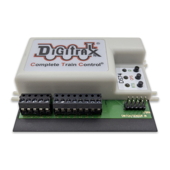
DS74
Features:
▪
Quad LocoNet based Stationary decoder for operating four turnout control
motors.
▪
Configurable to support four 12V Pulse-Solenoid, four Slow-motion turnout
motors or eight layout Lights.
▪
Plug-in connectors for simple and easy installation and service.
▪
User configurable as 4 consecutive switch addresses in 2000+ switch range.
▪
Stabilized typical 12V output drive voltages.
▪
Easily configured with Option Switches and/or LocoNet based programming.
▪
Power input from 2mm DC jack, or DCC track voltages, 10V min to 22V max.
▪
Optional Capacitive Discharge configurable for balky pulse-solenoids.
▪
8 DS74 easy to setup Routes, with 8 Switch Entries each.
▪
8 input control lines; 4 for Switch/Output change and 4 DS/Sensor inputs.
▪
Additional advanced LocoNet Configuration modes using DT602 throttles.
Parts List
1 DS74 Stationary Decoder
1 Instruction Sheet
1.0 DS74 Quick Start - Solenoid Installation
The DS74 is simple to install and begin using on your LocoNet layout.
1.
Figure 1 shows the recommended factory default connections to operate
the DS74 on a LocoNet layout and controlling four e.g. Atlas or Bachmann
3-wire snap type 12V pulse-solenoid switch (SW) turnouts.
2.
Connect a PS14 DC or similar power supply to your DS74 via the DC cen-
ter-positive 2mm power jack. Power on the DC supply. The green ID LED
should light and will briefly wink OFF every 2 secs as a product 'heartbeat'
showing unit is powered and operational.
3.
Plug in an active LocoNet to a DS74 RJ12 connector. The red OPS LED will
light up showing connection. Any good LocoNet message seen will cause
DS74 OPS LED to blink OFF briefly.
4.
Press and hold down the ID button for about 3 seconds until the RTS and
OPS LEDs blink alternately, then release the ID button.
5.
From your system send a SW command to set the Base Board address as this
switch#. The OPS and RTS LEDs will stop blinking showing the DS74 has
set the unit's Base SW# to the switch number (SW#) you just sent.
6.
Operate turnouts with a switch# and direction Thrown (T)/Closed(C) at the
Base SW#, or the next 3 SW#'s in use for this DS74.
That's all that's required for installation of your DS74 on LocoNet!
© 2021 Digitrax, Inc.
Complete Train Control
Run Your Trains, Not Your Track!
Quad LocoNet Stationary/ Accessory decoder
for turnout control
— 1 —
.
1 10-pin pluggable input cable
www.digitrax.com
Advertisement
Table of Contents

Related Manuals for Digitrax DS74


Summary of Contents for Digitrax DS74
- Page 1 DS74 on a LocoNet layout and controlling four e.g. Atlas or Bachmann 3-wire snap type 12V pulse-solenoid switch (SW) turnouts. Connect a PS14 DC or similar power supply to your DS74 via the DC cen- ter-positive 2mm power jack. Power on the DC supply. The green ID LED should light and will briefly wink OFF every 2 secs as a product 'heartbeat' showing unit is powered and operational.
- Page 2 Figure 1: DS74 LocoNet DC in Solenoid Connections omplete rain ontrol To Track (Optional) 1/BRN TKB P+ RET P2+ 3R 2G 1G 1R SWITCH/SENSOR IN 10 pin header cable +COM +COM +COM +COM Figure 2: DS74 LocoNet DC in Slow Motion Connections...
- Page 3 3.0 Setup DS74 Ez-Routes: The DS74 has 8 internal Routes with up to 8 switch# and T/C direction Entries each. These can be set up as Ez-Routes using the RTS button and switch com- mands from a LocoNet throttle or connected PC.
- Page 4 4.0 Other DS74 Options: OPSW changes The DS74 configuration and behavior can be configured using 40 OPSW's. The Factory default OPSW settings will configure most common requirements. Press and hold the OPS button for about 3 seconds until the green ID and RTS LEDs blink alternately.
- Page 5 +5V voltage on the BLACK wire or pin10. If the DS74 is connected to LocoNet this will occur as a SW# message to make the change and notify the system it has occurred.
- Page 6 SN 9122. This is displayed in GREEN to indicate that it does NOT conflict with the second DS74 SN 3122 at Base address 5. This is true because the next free address is SW1+4 or SW0005, that second DS74 SN 3122 is set at or above.
- Page 7 DT602 plugged into LocoNet, press the; Menu>3>4 keys to enter Route Editor menu. If any DS74 is on LocoNet, the DT602 will beep after about one second and show "DS7x" routes at the D soft key position.
- Page 8 70mA. Total 8 Light/Lamp loads should be less than 280mA peak. Take care not to short any of the DS74; R/G output, P+ and RET leads, or connect to other voltages like Track power etc. This may cause damage not covered by Warranty.
Need help?
Do you have a question about the DS74 and is the answer not in the manual?
Questions and answers
Can you help me to set up a turnout on the DS74
@Robert Lorenzo
how to reset DS74 to factory settings?
To reset the Digitrax DS74 to factory settings, follow these steps based on the provided context:
1. Set CV08 to a value of 08:
- Place the DS74 on a dedicated programming track in service mode (direct mode preferred).
- Program CV08 = 08.
This will reset all the DS74's configuration variables (CVs) and settings back to factory defaults.
2. After programming CV08, it's recommended to power cycle the DS74:
- Turn the DS74's power off, then back on to ensure the reset fully takes effect.
3. Alternative Restart Method (if you can’t easily power cycle):
- Write CV7 = 00 to force a DS74 reboot without removing power.
### Additional notes:
- If the DS74 is not responding properly after reset, verify that it is in programming mode and that you are using a compatible throttle (like a DT602 or DT400 series) and system (like a DCS100).
- Be cautious when changing CVs like CV11–CV15 after the reset, because they control internal option switches (OPSWs) in groups of 8 bits.
Would you like me to also show you a simple diagram of the reset steps?
This answer is automatically generated