Table of Contents
Advertisement
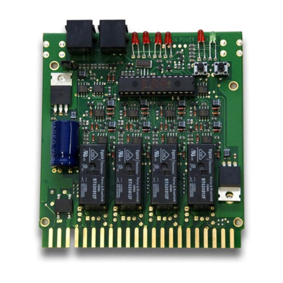
PM42
Power Manager For 4 Independent
Power Sub-Districts
Features
Cost effective power management for 4 power sub-districts.
Short circuit management or auto-reversing for each sub-district.
Short circuit management increases layout reliability by preempting booster
shutdown when a short circuit is detected by the PM42. This minimizes dis-
ruptions to operations by automatically restarting layout operation when the
short circuit is cleared.
User selectable short circuit detection sensitivity lets you adjust the PM42 to
optimize operation with other equipment on your layout.
Auto-reversing manages polarity mismatches on reversing track sections.
Trains move through reversing sections on your layout automatically, without
manually throwing electrical toggle switches or adding another booster.
Connect your PM42 to LocoNet & transmit information to your LocoNet
system.
No locomotive wiring modifications needed.
An external power supply is needed to run the PM42 (12-18V AC or DC
125mA minimum output). Digitrax PS14 power supply is sold separately
©2013 Digitrax, Inc.
Complete Train Control
Run Your Trains, Not Your Track!
www.digitrax.com
Short Circuit Management or
Auto Reversing
All Scales
Advertisement
Table of Contents

Related Manuals for Digitrax PM42


Summary of Contents for Digitrax PM42
- Page 1 Connect your PM42 to LocoNet & transmit information to your LocoNet system. No locomotive wiring modifications needed. An external power supply is needed to run the PM42 (12-18V AC or DC 125mA minimum output). Digitrax PS14 power supply is sold separately ©2013 Digitrax, Inc.
-
Page 2: Table Of Contents
4.0 PM42 Wiring 5.0 PM42 Option Switch (OpSw) Set Up 5.1 PM42 Trip Current 5.2 Setting the Short Circuit Sensitivity of the PM42 5.3 Setting the PM42 for Auto-Reversing Operation 6.0 Using your PM42 on LocoNet 6.1 Setting the PM42’s board address: 7.0 Troubleshooting... -
Page 3: Introduction
PM42) can power more than one PM42 as long as it provides 125mA per PM42 and is not used to power any other device. DO NOT share a power sup- ply between your PM42 and any command station or booster on the layout. -
Page 4: Auto-Reversing
3.2 Auto-Reversing When a train enters a PM42 reverse section sub-district that is set up for "Auto- Reversing" and there is a polarity mis-match, the PM42 will automatically change the polarity of that sub-district and the train will continue to run through the reversing track section. -
Page 5: Pm42 Wiring
2. Connect the wires from the booster's Rail A & Rail B outputs to the Rail A & Rail B inputs for one section of the PM42 that will be powered by that booster. (See TABLES I & II for connection details for each PM42 section). - Page 6 Rail B connection to booster for PM42 Section 4 Do Not Connect Do Not Connect Do Not Connect * Note if Auto-reversing is not set up for any given PM42 section, do not connect REV A or REV B Pins...
- Page 7 PM42 Section 4 RAIL B Rail B connection to booster for PM42 Section 4 GROUND** Connect to booster ground/case Do Not Connect Do Not Connect **Ground (Pin B or X) must be made to booster for correct PM42 operation.
- Page 8 Diagram 1: PM42 Wiring Examples Example A 1 Booster - 4 Short Circuit Managers Factory Settings (DEFAULT) Booster Rail B Pins 7, 11, 15 ,19 Booster Rail A Pins 4, 8, 12, 16 12-18V AC Pin 3 TOP ROW 44 Pin Connector...
- Page 9 NOTE: To complete auto- reversing set up you must wire the layout as shown here and also set the appropriate OpSw to activate auto- r eversing in your PM42. See Table IV for appropriate OpSw. TRACK OUTPUTS Example D Booster #1 - 2 Short Circuit Managers...
-
Page 10: Pm42 Option Switch (Opsw) Set Up
5.0 PM42 Option Switch (OpSw) Set Up The PM42 OpSw settings are used to set up the PM42 for setting up the trip current, short circuit management (including sensitivity), and/or auto-reversing. Follow the steps outlined below to set up OpSws according to the TABLES below. -
Page 11: Pm42 Trip Current
5.1 PM42 Trip Current The PM42 factory default for trip current is set at 3 amps. This is the current that all Digitrax boosters can provide briefly under fault conditions with ade- quate track wiring. A 3 amp trip current will work for most boosters and lay- outs. -
Page 12: Setting The Short Circuit Sensitivity Of The Pm42
Slow short circuit detection is best for layouts using heavy lamp loads and/or slower boosters. Standard short circuit detection works for most HO locos on most Digitrax lay- outs. Faster short circuit detection can be used with most HO & N scale locos on most Digitrax layouts. -
Page 13: Setting The Pm42 For Auto-Reversing Operation
PM42. 6.1 Setting the PM42’s board address: 1. Connect a Digitrax DT series throttle to the LocoNet port on your PM42. 2. If the PM42 is not connected to a working LocoNet (via a 6 conduc-... -
Page 14: Troubleshooting
LocoNet cable), position the LocoNet termination jumper, locat- ed behind the RJ12 sockets, across both pins. If the PM42 is con- nected to a working LocoNet, you do not need to use the LocoNet termination jumper. 3. Press and hold the "ID" button behind the green LED for about 1 sec- ond. -
Page 15: Warranty And Repair Information
-Consult the dealer or an experienced radio/TV technician for help. Note that any modifications to the equipment not expressly approved by Digitrax voids the user's authority to operate under and be in compliance with CFR 47 rules, as administered by the Federal Communication Commission. - Page 16 PM42 Power Manager Super Super Available Computer Interface Computer Interface Decoder Programmer Decoder Programmer Sound Programmer Sound Programmer 2443 Transmitter Road Panama City, FL 32404 www.digitrax.com : techsupport@digitrax.com suPPoRT : repair@digitrax.com RePaiR Made in U.S.A.
Need help?
Do you have a question about the PM42 and is the answer not in the manual?
Questions and answers