Table of Contents
Advertisement
Quick Links
1. Use of Operation Manual
Please read through and understand this Operation Manual
before operating the product. After reading, always keep the
manual nearby so that you may refer to it as needed. When
moving the product to another location, be sure to bring the
manual as well.
2. Safety instructions
2.1. Safety Terms and Symbols
This chapter contains important safety instructions that you
must follow when operating the instrument and when keep-
ing it in storage. Read the following before any operation
to insure your safety and to keep the best condition for the
instrument.
The following safety symbols may appear in this manual or
on the instrument:
WARNING - Identifies conditions or practices that could
result in injury or loss of life.
CAUTION - Identifies conditions or practices that could
result in damage to the instrument or to other properties.
AX-3003P AX-6003P
DANGER - High voltage
ATTENTION - Refer to the manual
Earth (ground) terminal
Protective conductor terminal
2.2. Safety Guidelines
•
•
•
•
•
Before plugging into local AC mains, check and make
sure that the output voltage is compatible to the load. (It
is suggested to disconnect a load before plugging into
local AC mains.
Do not use this instrument near water.
Do not operate or touch this instrument with wet hands.
Do not open the casing of the instrument when it is
connected to AC mains.
The max.output voltage of the instrument may be over
60VDC, avoid touch the metal contact part of the output
terminals.
Advertisement
Table of Contents

Related Manuals for AXIOMET AX-3003P


Summary of Contents for AXIOMET AX-3003P
- Page 1 AX-3003P AX-6003P 1. Use of Operation Manual DANGER - High voltage Please read through and understand this Operation Manual before operating the product. After reading, always keep the manual nearby so that you may refer to it as needed. When...
-
Page 2: Operation Notes
• Do not use the instrument in an atmosphere which • To clean the power supply, use a soft cloth dampened in contains sulfuric acid mist or other substances which a solution of mild detergent and water. Do not spray cause corrosion to metal. -
Page 3: Basic Operations
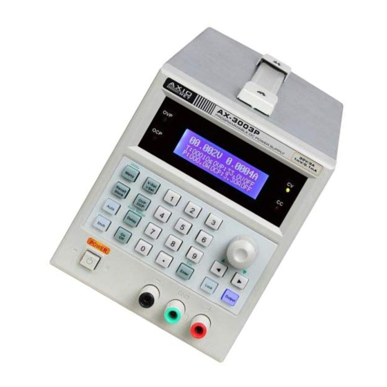
1. Power switch OVP indicator: The OVP light turns green to indicate the 2. Function key and Numeric keypad over voltage protection function is on. 3. OCP indicator OCP indicator: The OCP light turns red to indicate the over 4. OVP indicator current protection function is on. -
Page 4: Parameters Setup
The data can have only one decimal point. If one data input peat this operation, a series of voltage with equal interval has more than one decimal point, only the first one is valid. can be generated. The same procedure can be used for the After input a new value, press key [Enter] to validate it. - Page 5 8.2. Output Current Setting ter] to complete OCP setting. Press key [V-Set/I-Set] until “Current” is shown on the LCD. Setting method 2: Press [Number knob (current value)] to Setting method 1: Press [Number key (current value)] [En- change OCP setting immediately. ter] to set output current.
- Page 6 8.14. Recall the Setting Data from the Memory For example: Set the step voltage to 10.000V. Bank Press [1] [0] [.] [0] [0] [0] [Enter]. Press key [Menu] or [Recall/Store] until “Utility Recall” is shown on the LCD, use the number key to input the memory address to recall the data, then press [Enter] to complete the 8.10.
- Page 7 8.22. Lock [Enter] to set start memory address. Setting method 2: Press [Number knob (memory address)] The Lock key is for locking up the panel setting. When the to change start memory address immediately. key light turns on, the other key and knob is disabled except For example: Set the start memory address to 0.
- Page 8 (the knob can be used together with [<] or [>] to adjust the Constant current mode confirmation. resolution). Check whether the CC indicator is on or not to make sure the Set the desired output voltage value. output operation is under the constant current mode. If the Press [V-Set/I-Set] until “Voltage”...
-
Page 9: Remote Control
Press [Output] to turn on the output. Load regulation:≤0.01%+3mV (I≤3A) / ≤0.02%+5mV Under this mode, it can monitor the current operation setting (I>3A) address, left time and left cycle. Recovery time:≤100us (50% load change, minimum load 0.5A) Ripple & Noise:≤1mV rms (I≤3A) (5Hz~1MHz) / ≤2mV rms (I>3A) (5Hz~1MHz) 9. - Page 10 Dimension: 296 (D) ×126 (W) ×143 (H)mm Weight:≤5.5kg Maximum Setting Value Model / AX-3003P / AX-6003P Output range Item / 30V/3A / 60V/3A Output voltage / 32V / 62V Output current / 3.2A / 3.2A...
Need help?
Do you have a question about the AX-3003P and is the answer not in the manual?
Questions and answers
What is cal step shows in screen