Table of Contents
Advertisement
Quick Links
- Set-up & installation
- Use
- Maintenance
- Accessories
We manufacture
in Germany!
USER MANUAL
Carefully read these instructions before starting
and using your log loader!
HRZ FIX Euro/Kombi
Südharzer Maschinenbau GmbH
Helmestraße 94 ∙ 99734 Nordhausen/Harz
Receptionist:
Internet: www.bgu-maschinen.de
e-mail: info@bgu-maschinen.de
03631/6297-0
6297-111
Advertisement
Table of Contents

Related Manuals for BGU HRZ FIX Euro/Kombi


Summary of Contents for BGU HRZ FIX Euro/Kombi
- Page 1 USER MANUAL Carefully read these instructions before starting and using your log loader! HRZ FIX Euro/Kombi - Set-up & installation - Use - Maintenance - Accessories We manufacture in Germany! Südharzer Maschinenbau GmbH Helmestraße 94 ∙ 99734 Nordhausen/Harz Receptionist: 03631/6297-0 6297-111 ...
-
Page 2: Table Of Contents
CONTENT Content General information 1.1 About this manual 1.2 Delivery and transport claims Safety pictograms and warning labels Safety 3.1 General safety rules and occupational safety Operation 4.1 Mandatory application field 4.2 Preliminary controls before use 4.2.1 Mounting the loader to the tractor 4.2.2 Assembling an additional control valve unit 4.3 Start-up 4.4 Attachments... -
Page 3: General Information
GENERAL INFORMATION Dear customer, thank you very much for your trust and preference in choosing our equipment and joining the number of our best customers in the world. We are confident that our equipment will be up to all your expectations and assure you a long lasting quality and performance. - Page 4 All transport damages must be notified within latest 2 days from de- livery. Therefore delivery must be collected and inspected within this term. Later claims shall be disregarded. In case of assumed but not visually clear transport damages make sure to mark the following sen- tence on the delivery bill: „Reserved delivery due to assumed trans- portation damages“.
-
Page 5: Safety Pictograms And Warning Labels
SAFETY PICTOGRAMS AND WARNING 1. Pictogram: „Grapple Release/Grasp“ 2. Pictogram „Hydr. Motor“ 3. Pictogram „Swivel Arm to the right/left“ 4. Pictogram „Extendible Arm, Retract/Extend“ 5. Pictogram „Retract/Extend Upper Pin“ 6. Pictogram „Pivotal Hanger UP/DOWN“ 8. Pictogram „Boom Lift UP/DOWN“ 8. Machine safety label „Read the instructions before start-up“... - Page 6 9. Identification label „Product identification“ This label shows the company details of the manufacturer and the main machine technical data. 10. „BGU-Maschinen“ Manufacturer‘s Logo 11. Safety pictogram „Do not infringe the dangerous zone“ Avoid standing in the dangerous zone between the tractor and the log loader.
-
Page 7: Safety
SAFETY Strictly perform installation, set-up, maintenance, cleaning and transportation with the engine switched off and all moving parts firmly secured against accidental operation. Immediately disconnect power off the machine in case of any eventual fault or trouble. The user shall strictly comply with these operation, set-up, mainte- nance, repair and trouble-shooting instructions in order to assure safe operation and no damages to the equipment. -
Page 8: General Safety Rules And Occupational Safety
• Perform logs piling and general rolling operations with extreme care and at very low tractor speed. DANGER: watch for timber/branches that may fall on or enter the operator’s compartment. • Changing the length setting of the extendible arm may be strictly performed with the butt plate lowered on ground, the grapple clamped and the tractor engine switched off. - Page 9 • Do not allow anybody on the loader during loading or travel opera- tions! • Connect the equipment in compliance to these instructions and the applicable provisions! • Work defensively. Think ahead and anticipate hazards. Take special care in connecting/disconnecting eventual attachments to/from the tractor! •...
-
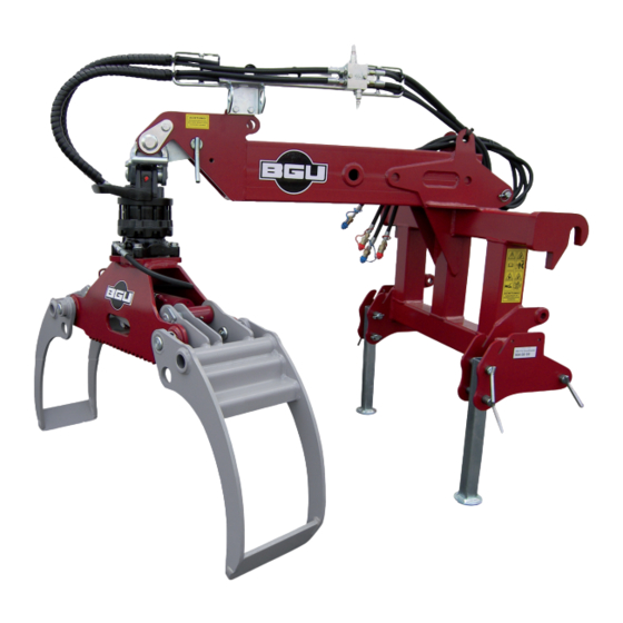
Page 10: Operation
OPERATION 4.1 Mandatory application field Grapple loaders are strictly designed for woodlot owners to pull, handle and manipulate timber logs. They are purposely designed with attach- ment lungs to allow for very practical pulling operations by means of log- ging chains. The maximum working pressure of the grapple is 180 bar. The rotator motor is equipped with standard built-in pressure relief valve set by manufacturer at 170 bar so that no further adjustments are required by operators on site. -
Page 11: Assembling An Additional Control Valve Unit
Südharzer Maschinenbau GmbH will accept no liability for the state and conditions of your tractor three-point linkage. Make sure to install the loader so that no damage can occur to the driver‘s cab during off- road travel or with lifted hydraulics. 4.2.2 Assembling an additional control valve unit As soon as a hydraulic function is no longer required, you can use it to control operation of the hydraulic upper link. -
Page 12: Attachments
• Check the fixation bolts and the respective cotter pins before start-up. • Close the grapple and set it across travel direction before operating the unit without a load (unloaded state). Close the grapple and position it across the travel direction when tra- velling without a load. -
Page 13: Hydraulic System
HYDRAULIC SYSTEM • DANGER: the hydraulic system operates at very high pressure! • Mind the correct connection of all hydraulic hoses, as you perform branching of the hydraulic cylinders and of the motors! • For due connection of the hydraulic hoses to your tractor hydraulics make su- re that no pressure is available on both the tractor and the attachment side! •... -
Page 14: Repairs And Maintenance
• While PTO-powering your loader, ensure that the number of PTO- shaft rpm matches the travel speed and that the direction of the revo- lution changes while performing backward travel! • Do not engage the PTO without priory switching the engine on! •... -
Page 15: Ordinary Maintenance
7.1 Ordinary maintenance The following services must be provided at 10 hour operation intervals: • Lubricating all moving parts by means of the respective nipple head • Recommended lubricant: universal lub grease • Lubricating the extendible load lifting arm using a grease brush •... -
Page 16: Dismounting And Discarding An Obsolete Loader
DISMOUNTING AND DISCARDING AN OBSOLETE MACHINE When the machine is fully obsolete and cannot be of any longer use, it should be duly dismounted ahead of discarding. Certain components need deactivation and dismantling in order to assure that no further use is made by other parties and that no worn out parts are recycled for other applications. -
Page 17: Technical Specifications
10. TECHNICAL SPECIFICATIONS Technical specification Unit of measurement Attaches to any front-mount or to a rear, Category II three-point hitch Tractor power requirement 40 - 90 Grapple model HG 1300 Max gripping width 90-1280 Clamping force Grapple model HG 1700 (optional) Max gripping width 90-1680 Clamping force... -
Page 18: Other Areas Of Possible Hazards
11. OTHER AREAS OF POSSIBLE HAZARD 11.1 Mechanical dangers Possible dangers related to machine moving parts are minimized by means of suitable safeties and protections that cannot be removed unless special tools and equipment are used. Do not attempt to remo- ve or by-pass any of the machine inbuilt safeties. -
Page 19: Spare Parts List For Hrz Fix-Euro/Kombi
13. HRZ FIX-EURO/KOMBI, SPARE PARTS LIST Description Number of Art. Nr. Pos. pcs. BG hose, fairlead 22820 BG frame Euro Kombi 22256 55994 Category 1, lower link pins Clamp hanger 22387 Upper link pins 55991 23842 Grapple HG 1300 BG standard pin 30-123 22829 BG Joint 22335... -
Page 20: Spares For Log Grapples Model 1300
13.1 Grapple 1300, Spare Parts List... - Page 21 Description Quantity Dimensions Pos. Grapple housing 1300, (complete 20034 assembly) Custom bolts 40-178 22355 22356 Custom bolts 40-60 80/40-305 Hydraulic cylinder 55878 Small claw 22354 22353 Large claw Parallel guide (complete 23899 assembly) DIN 71412 AM 6x1 Ball nipple (on the cylinder) 51163 55936 DIN 7346...
-
Page 22: Spares For Log Grapples Model 1700 (Optional)
13.2 Optional Grapple mod. 1700, Spare Parts List... - Page 23 Description Number of Size Pos. pcs. Grapple housing mod. 1700, 24033 (Complete assembly) Parallel guide (complete 23899 assembly) Custom bolts 40-60 22356 22535 Large claw Small claw 22354 55878 80/40-305 Hydraulic cylinder Standard bolts 40-178 22355 DIN 7346 Dowel pin 55936 55937 DIN 71412...
-
Page 24: Spares For Top Slewing Arrangement (Optional)
13.3 Optional top slewing arrangement, Spare Parts List Description Number of Size Pos. pcs. 22822 Choke 22343 Connecting link 22341 55939 60/30-195 Hydraulic cylinder 40x30 Collar-less Sleeve 55909 Lock ring for shafts 51676 DIN 471 51163 DIN 71412 AM 6x1 Ball nipple Side link 22340... -
Page 25: Spares For Bucket Assembly Model 1500 (Optional)
13.4 Optional bucket assembly mod. 1500, Spare Parts List Description Number of Size Pos. pcs. 22201 Bucket assembly DIN 934 Hex nut 51595 51480 DIN 933 M12x40 Hex screw... -
Page 26: Spares For Pivotal Hanger For Claws Rotation
13.5 Pivotal hanger for claws rotation, Spare Parts List Pos. Nr. Number of Description pcs. BG Tension spring, Mounting length BG shaft BG Grapple link Hex nut DIN 934 - M 16 Hex screw DIN 931-M16x120 T-grooved bolt 2 Hex nut DIN 934 - M 12 T-perforated plate... -
Page 27: Spares For Rotator (Optional)
13.6 Optional rotator, Spare Parts List... - Page 28 Description Number of Size Pos. pcs. MTR 46.01 LA Head MTR 46.02 B MTR 46.006-01 Rotor shaft Stator MTR 46.007 MTR 46.012 LA Flange Guard MTR 46.03 LA MTR 46.008 MTR 30.015-02 Spacer MTR 45.011 MTR 45.010 Washer Shim MTR 45.014-01 Lock screw MTR 45.015-01 MT 0210...
-
Page 29: Ec Statement Of Compliance
14. EC – STATEMENT OF COMPLIANCE In accordance with the EC Machine Directive No. 42/2006 and EMV (Low Voltage) Directive 108/2004 We hereby declare that the equipment described in this manual responds in full to the actual version brought on the market. We, the manufacturer further declare that this equipment was duly designed and manufactured in accordance with the actual European Safety and Health Standards settled by the relevant EEC directives as well as the latest electromagnetic standards issued by the European Council of 3.5.89 and later enforced by all member states. - Page 32 Subject to changes Südharzer Maschinenbau GmbH Helmestraße 94 ∙ 99734 Nordhausen/Harz Form: 904.17.02.2009- Rev. A Service-Tel. 03631/6297-104 ∙ Fax 03631/6297-111 Internet: www.bgu-maschinen.de e-mail: service@bgu-maschinen.de...
Need help?
Do you have a question about the HRZ FIX Euro/Kombi and is the answer not in the manual?
Questions and answers