Table of Contents
Advertisement
Available languages
Available languages
Quick Links
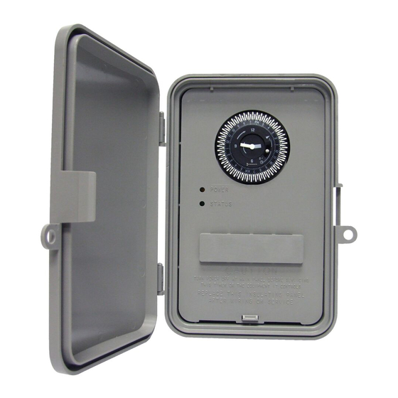
GM40AV Series General Purpose Electromechanical Commercial Time Switches
Installation & Operating Instructions
Risk of Fire or Electric Shock
WARNING
• Disconnect power at the circuit breaker(s) or disconnect switch(es) before installing or servicing.
• More than one circuit breaker or disconnect switch may be required to de-energize the equipment before
servicing.
• Do not use the manual shut-off position of the timer for equipment servicing. Always disconnect the power
at the circuit breaker(s) or disconnect switch(es).
• Installation and/or wiring must be in accordance with national and local electrical code requirements.
• This Time Switch is designed to control one or two single phase loads. Do not use to directly control three
phase loads. Consult a qualified electrician if you are required to control three phase equipment.
• Some terminals in the Time Switch may be energized even if the yellow and green LED indicators are OFF.
• The circuit conductors shall have an ampacity not less than the maximum total load to be controlled.
• For all connections, use COPPER conductors ONLY – min. #8 AWG wires for 40 A loads, or #10 AWG wires
for 30 A loads, min. 90°C (194°F)
• Over current protection shall have an interrupting rating sufficient for the application control circuit voltage
and the total load current of the equipment being controlled.
• A fuse or circuit breaker shall be connected in series with each ungrounded conductor (and shall be able to
simultaneously open each conductor.
• Check all terminals and wires with an appropriate voltage meter before touching.
• This enclosure does not provide grounding between conduit connections. When metallic conduit is used,
you must also install grounding type bushings and jumper wire, in accordance with the (NEC) National
Electrical Code requirements.
• For outdoor locations or wet locations (rain-tight), conduit hubs that comply with requirements of the
UL514B (standard for fitting conduit and outlet boxes) are to be used.
• Replace plastic insulator covering terminals before powering ON.
NOTICE
• Rotate timer dial clockwise only.
• Jumper wires are not included.
• Alterations or modifications to the device will void warranty
Read Instructions completely before installation and retain this booklet for future reference.
INSTALLATION INSTRUCTIONS
1. Open door and remove the interior protective cover by releasing the spring latch. (See Figure 1)
2. Remove the printed circuit board by releasing the spring latch holding the bottom of the board.
(see Figure 1)
3. Select knockouts to be used. Remove the inner 1/2" knockout by inserting a flathead screwdriver
in the slot and carefully punch the knockout loose. Remove slug. If 3/4" knockout is required,
remove the outer ring with pliers after removing the 1/2" knockout. Smooth edge with knife, if
necessary.
4. Place the enclosure in the desired mounting location, and mark the three mounting holes (refer to
Figure 2 for dimensions). Install the top screw first with one of the supplied spacers, and then hang
the enclosure by the keyhole. Drive the remaining two screws at the bottom of the enclosure
through the mounting holes while passing each screw through one of the supplied spacers and in
to the wall.
5. Connect conduit hubs to conduit before connecting the hubs to the enclosure. After inserting hubs
into enclosure, carefully tighten hub lock nut. Do not over-torque.
6. Replace printed circuit board making sure to engage spring latch at the bottom of PCB.
7.
Wire in accordance with national and local electrical and safety codes (see wiring diagrams).
8. Grounding: Terminate all ground wires to the ground lug inside the case at the bottom of the
enclosure.
9. Replace interior protective cover.
10. Close the enclosure door.
PROGRAMMING INSTRUCTIONS
SETTING THE CLOCK TIME
Rotate the program dial gradually clockwise until the time of day on the outer dial is nearly aligned with
the triangle marker at the 2 o'clock position. Then set time to the minute by rotating minute hand
clockwise until the time of day (and AM or PM) on the outer dial is aligned with the triangle marker on
the inner dial.
SETTING ON/OFF TIMES
Move the white tab (tripper) on the outer dial outward at the start of the desired ON period. Move each
adjacent tab outward until the desired OFF time is reached. (See Fig. 3)
ELECTRICAL RATINGS
NO Contacts:
WIRING CONNECTIONS:
40 A Resistive, 120-277 VAC
Screw box lug terminals
30 A Ballast, 120 VAC
ENVIRONMENTAL RATINGS:
20 A Ballast, 277 VAC
Operating Temperature Range:
15 A Tungsten, 120 VAC
-40° F to 131° F (-40° C to 55° C) Non "Q" Models
300 VA Pilot Duty, 120-240 VAC
-4° F to 131° F (-20° C to 55° C) "Q" Models
1 HP, 16 FLA, 90 LRA @ 120 VAC
Operating Humidity:
2 HP, 12 FLA, 52 LRA @ 208-277 VAC
10-95% RH, non-condensing
NC Contacts:
ENCLOSURE DIMENSIONS:
30 A Resistive, 120-277 VAC
8.795" H x 6.631" W x 2.935" D
10 A Ballast, 277 VAC
2 A Tungsten, 120 VAC
SHIPPING WEIGHT:
1 HP, 12 FLA, 30 LRA @ 120 VAC
2 lbs.
2 HP, 10 FLA, 30 LRA @ 240 VAC
Interior
Timer Mechanism
Protective
Cover
Spring Latch
Figure 1 - PCB Latch
Green Status LED: ON
(Normally-open contacts closed)
TRIPPERS IN
Green Status LED: OFF
(Normally-open contacts open)
MANUAL OVERRIDE OPERATION
With the manual switch in the middle position, the GM40AV is in
automatic mode and will switch at the programmed times.
In the upper position "I", the load is continuously ON.
Figure 3
In the lower position, "O", the load is continuously OFF.
GM40AV SERIES TERMINAL DESIGNATIONS
208/240 VAC Application One Load
T
TIMER
L 1
L 2/N
NC
NO
L1
L2
120/277 VAC Application Two Loads
T
TIMER
L 1
L 2/N
NC
NO
L
N
6-1/8"
2-1/2"
Figure 2 - Rear View of Enclosure
with mounting hole dimensions
TRIPPERS OUT
COM
NC 2
NO 2
COM2
LOAD
#1
COM
NC 2
NO 2
COM2
LOAD
LOAD
#1
#2
Advertisement
Table of Contents

Related Manuals for Intermatic Grasslin GM40AV Series


Summary of Contents for Intermatic Grasslin GM40AV Series
- Page 1 GM40AV Series General Purpose Electromechanical Commercial Time Switches Installation & Operating Instructions ELECTRICAL RATINGS Risk of Fire or Electric Shock WARNING NO Contacts: WIRING CONNECTIONS: 40 A Resistive, 120-277 VAC Screw box lug terminals • Disconnect power at the circuit breaker(s) or disconnect switch(es) before installing or servicing. 30 A Ballast, 120 VAC •...
- Page 2 Série de GM40AV Commutateurs horaires commerciaux électromécaniques d’usage universel. Directives d’installation et de Fonctionnement CARACTÉRISTIQUES NOMINALES Risque d’incendie ou de choc électrique AVERTISSEMENT CONNEXIONS DU CÂBLAGE : Contacts NO : • Débrancher l’alimentation aux disjoncteurs ou interrupteurs généraux avant l’installation ou l’entretien. Bornes à...
- Page 3 Serie GM40AV Uso general Interruptores de tiempo electrómecanico comerciales Instrucciones de Instalación y Operación CAPACIDAD ELÉCTRICA NOMINAL ADVERTENCIA Riesgo de incendio o descarga eléctrica NO Contactos CONEXIONES DEL CABLEADO: • Desconecte la energía desde los disyuntores o los interruptores de desconexión antes de realizar la instalación o Resistencia de 40 A a 120-277 V CA Terminales de puesta a tierra en caja con tornillo el mantenimiento.
- Page 4 LIMITED WARRANTY Warranty service is available by either (a) returning the product to the dealer from whom the unit was purchased or (b) completing a warranty claim online at www.intermatic.com. This warranty is made by: Intermatic Incorporated, Customer Service 1950 Innovation Way, Suite 300, Libertyville, IL 60048. For warranty service go to: http://www.Intermatic.
Need help?
Do you have a question about the Grasslin GM40AV Series and is the answer not in the manual?
Questions and answers