Table of Contents
Advertisement
Available languages
Available languages
Quick Links
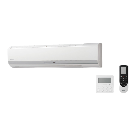
SPLIT TYPE ROOM AIR CONDITIONER
INDOOR UNIT
OUTDOOR UNIT
INSTALLATION MANUAL
UNITÉ INTÉRIEURE
UNITÉ EXTÉRIEURE
UNIDAD INTERIOR
UNIDAD EXTERIOR
AY-X36RU
AE-X36RU
CLIMATISEUR INDIVIDUEL EN DEUX PARTIES
MANUEL D'INSTALLATION
ACONDICIONADOR DE AIRE TIPO SPLIT
MANUAL DE INSTALACIÓN
AYX36RU_IM_3_lang.indb 1
2014-09-12 07:59:31
Advertisement
Table of Contents

Related Manuals for Sharp AY-X36RU


Summary of Contents for Sharp AY-X36RU
- Page 1 SPLIT TYPE ROOM AIR CONDITIONER INDOOR UNIT OUTDOOR UNIT INSTALLATION MANUAL UNITÉ INTÉRIEURE UNITÉ EXTÉRIEURE UNIDAD INTERIOR UNIDAD EXTERIOR AY-X36RU AE-X36RU CLIMATISEUR INDIVIDUEL EN DEUX PARTIES MANUEL D’INSTALLATION ACONDICIONADOR DE AIRE TIPO SPLIT MANUAL DE INSTALACIÓN AYX36RU_IM_3_lang.indb 1 2014-09-12 07:59:31...
-
Page 2: Safety Precautions
Carefully read and follow these instructions for smooth and trouble-free installation. ENGLISH SAFETY PRECAUTIONS • Installation must be made in accordance with the installation • Tighten the flare nut with a torque wrench according to the specified manual by qualified service personnel. method. Incorrect work will cause electric shock, water leak, fire. If the flare nut is tightened too hard, the flare nut may be broken after a long time and cause refrigerant gas leakage. -
Page 3: Connecting The Cable To The Indoor Unit
PIPING Max. piping Max. height Min. piping Additional refrigerant length:A difference:B length Piping length exceeds 24.6 ft (7.5 m) 98.4 ft (30 m) 32.8 ft (10 m) 9.8 ft (3 m) 0.5 oz/ft (50 g/m) • Standard piping length is 24.6 ft (7.5 m). Trap •... - Page 4 SETTING UP THE INDOOR UNIT Piping route For directions 1, 2 and 5, cut out the specific zone without leaving any sharp edge. (Keep the cut-out plate for possible future use.) Plate Plate Cut the plate along notch. Plate Mounting the indoor unit...
-
Page 5: Outdoor Unit Installation
OUTDOOR UNIT INSTALLATION Installation dimension 24 inch (609 mm) Referring to the figure, firmly fasten the outdoor unit with bolts. 15.7 inch (399 mm) Connecting the drain hose In the heating mode, the outdoor unit discharges water due to defrosting from its Drain hole (for the drain hose adapter) drain hole. -
Page 6: Connecting The Cable To The Outdoor Unit
CONNECTING THE CABLE TO THE OUTDOOR UNIT • Use a solid or stranded wire. Connecting cable Power supply cable Connecting cable: AWG14 Power supply cable: AWG10 4.7 inch (120 mm) 2.4 inch (60 mm) • Use copper wire. 2.0 inch (50 mm) 2.0 inch (50 mm) •... -
Page 7: Items To Check
10 ITEMS TO CHECK Is the specified power supply voltage used? Is the connecting cable fixed to terminal board firmly? Is the earth wire connected properly arranged? Is the drainage properly? Is the indoor unit hooked to the mounting plate firmly? Is there any gas leakage at the pipe connection? Is the cooling/heating operation normal? Explanation to customer Explain to the customer how to use and maintain the system, referring to the operation manual. -
Page 8: Consignes De Sécurité
Nous vous recommandons de lire attentivement ces instructions pour vous assurer une installation facile et sans problème. FRANÇAIS CONSIGNES DE SÉCURITÉ • L'installation doit être effectuée par du personnel qualifié, en respectant • Serrez l'écrou évasé avec une clé dynamométrique en suivant la méthode les instructions du manuel d'installation. spécifiée. Des travaux incorrects posent un risque d'électrocution, de fuite d'eau et d'incendie. Si l'écrou évasé est trop serré, il peut casser après une longue durée d'utilisation et provoquer une fuite de gaz réfrigérant. - Page 9 TUYAUTERIE Longueur de tuyau- Différence de Longueur de Réfrigérant additionnel terie max. : A hauteur max. : B tuyauterie min. La longueur de tuyauterie excède 7,5 m (24,6 ft) 30 m (98,4 ft) 10 m (32,8 ft) 3 m (9,8 ft) 50 g/m (0,5 oz/ft) •...
-
Page 10: Installation De L'unité Intérieure
INSTALLATION DE L'UNITÉ INTÉRIEURE Acheminement des tuyaux Pour les points 1, 2 et 5, découpez la partie adé- quate en veillant à ne laisser aucun angle coupant. (Conservez la partie découpée pour une éventuelle utilisation future.) Plaque Plaque Coupez la plaque le long Plaque des pointillés. -
Page 11: Installation De L'unité Extérieure
INSTALLATION DE L’UNITÉ EXTÉRIEURE Dimensions de l'installation 609 mm (24 po) En vous reportant au schéma, fixez fermement l’unité extérieure avec les 399 mm (15,7 po) boulons. Raccordement du tuyau de vidange Trou de vidange (pour l'adaptateur du tuyau de vidange) En mode chauffage, l'unité extérieure décharge l'eau de dégivrage au niveau du trou de vidange. -
Page 12: Branchement De L'alimentation
RACCORDEMENT DU CÂBLE À L'UNITÉ EXTÉRIEURE • Utilisez un fil massif ou tressé. Câble de connexion Câble d'alimentation Câble de raccordement : AWG14 Câble d'alimentation : AWG10 120 mm (4,7 po) 60 mm (2,4 po) • Utilisez un fil en cuivre. 50 mm (2,0 po) 50 mm (2,0 po) •... - Page 13 10 POINTS A VÉRIFIER La tension d'alimentation est-elle bien adaptée ? Le câble de raccordement est-il bien connecté fermement à la borne ? Le câble de mise à la terre est-il correctement installé ? L'évacuation est-elle adéquate ? L'unité intérieure est-elle fixée fermement à la plaque de fixation ? Le raccord des tuyaux présente-t-il une fuite de gaz ? Les fonctions de refroidissement ou de chauffage fonctionnent-elles correctement ? EXPLICATIONS AU CLIENT...
-
Page 14: Precauciones De Seguridad
Para una instalación rápida y sencilla, lea y siga estas instrucciones atentamente. ESPAÑOL PRECAUCIONES DE SEGURIDAD • La instalación debe llevarla a cabo personal cualificado siguiendo el • Apriete la tuerca cónica con la llave de torsión siguiendo el método manual de instalación. especificado. Si la instalación no es correcta, pueden producirse descargas eléctricas, Si la tuerca cónica se aprieta demasiado, podría romperse con el tiempo y originar fugas de agua o incendios. - Page 15 TUBERÍA Longitud máx. Diferencia máx. Longitud mín. Refrigerante adicional de tubería: A de altura: B de la tubería La longitud de la tubería supera los 7,5 m (24,6 pies) 30 m (98,4 pies) 10 m (32,8 pies) 3 m (9,8 pies) 50 g/m (0,5 oz/ft) •...
-
Page 16: Instalación De La Unidad Interior
INSTALACIÓN DE LA UNIDAD INTERIOR Trazado de las tuberías Para las direcciones 1, 2 y 5, corte la zona específi- ca sin dejar ningún borde cortante. (Guarde la placa recortada; puede serle útil poste- riormente). Placa Placa Cortar la placa a lo largo Placa de la muesca. -
Page 17: Instalación De La Unidad Exterior
INSTALACIÓN DE LA UNIDAD EXTERIOR Dimensión de la instalación 609 mm (24 pulg.) Sujete firmemente la unidad exterior con pernos, como se indica en la figura. 399 mm (18,7 pulg.) Orificio de desagüe (para el adaptador Conexión de la manguera de desagüe de la manguera de desagüe) En el modo de calefacción, la unidad exterior descarga de agua desde su orificio de des- agüe debido la descongelación. -
Page 18: Sistema De Alimentación
CONEXIÓN DEL CABLE A LA UNIDAD INTERIOR • Utilice cable rígido o flexible. Cable de conexión Cable de alimentación Cable de conexión: AWG14 Cable de alimentación: AWG10 120 mm (4,7pulg.) 60 mm (2,4 pulg.) • Utilice cable de cobre. 50 mm (2,0 pulg.) 50 mm (2,0 pulg.) •... -
Page 19: Comprobación De La Instalación
10 COMPROBACIÓN DE LA INSTALACIÓN ¿Se está utilizando el voltaje de alimentación especificado? ¿Está firmemente sujeto el cable de conexión al terminal de conexiones eléctricas? ¿Está correctamente conectado el cable de toma de tierra? ¿El desagüe drena correctamente? ¿Está firmemente sujeta la unidad interior a la placa de montaje? ¿Existe alguna fuga de gas en la conexión de la tubería? ¿Caliente y enfría normalmente la unidad? Explicación al cliente... - Page 20 AYX36RU_IM_3_lang.indb 7 2014-09-12 07:59:44...
Need help?
Do you have a question about the AY-X36RU and is the answer not in the manual?
Questions and answers