
Related Manuals for Ferroli OMNIA S 3.2


Summary of Contents for Ferroli OMNIA S 3.2
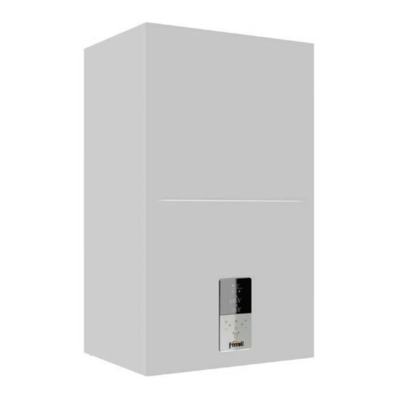
- Page 1 OMNIA S 3.2 WAAL-HUNG INDOOR UNITS FOR REVERSIBLE SPLIT HEAT PUMPS WITH DC INVERTER COMPRESSOR INSTALLATION, MAINTENANCE AND USER MANUAL...
- Page 2 OMNIA S 3.2 • Read the warnings in this instruction booklet carefully since they pro- • After unpacking, check the good condition of the contents. The packing vide important information on safe installation, use and maintenance. materials are potentially hazardous and must not be left within the •...
-
Page 3: Table Of Contents
OMNIA S 3.2 SUMMARY 1. SAFETY PRECAUTIONS ....................4 8.3 Switching ON and OFF DHW and plant ............... 41 1.1 Special requirements for R32 refrigerant ............... 5 8.4 HEAT, COOL and DHW setpoint settings ..............42 1.2 Information servicing ....................12 8.5 User menu ........................ -
Page 4: Safety Precautions
OMNIA S 3.2 1. SAFETY PRECAUTIONS The precautions listed here are divided into the following types. They are quite important, so be sure to follow them carefully. Meanings of DANGER, WARNING, CAUTION and NOTE symbols. DANGER Indicates an imminently hazardous situation which if not avoided, will result in death or serious injury. -
Page 5: Special Requirements For R32 Refrigerant
OMNIA S 3.2 1.1 Special requirements for R32 refrigerant WARNING • Do NOT have refrigerant leakage and open flame. • Be aware that the R32 refrigerant does NOT contain an odour. WARNING The appliance shall be stored so as to prevent mechanical damage and in a well-ventilated room without conti- nuously operating ignition sources (example:open flames,an operating gas appliance) and have a room size as specified below. - Page 6 OMNIA S 3.2 Input from installer: - Area of adjacent room B (A Start ) (m roomB Use table 3 to calculate the Input from installer: total minimum floor area (A )requi- mintotal - Total refrigerant charge (m )(kg) red for the total refrigerant charge (m...
- Page 7 OMNIA S 3.2 The flow chart uses the following tables: Table. 2 - Maximum refrigerant charge allowed in a room A [m2] mmax [kg] 1,87 0,21 0,41 0,62 0,83 1,04 1,24 1,45 1,66 2,07 2,28 2,49 2,62 2,72 2,82 2,91...
- Page 8 OMNIA S 3.2 DANGER • Before touching electric terminal parts, turn off power switch. • When service panels are removed, live parts can be easily touched by accident. • Never leave the unit unattended during installation or servicing when the service panel is removed.
- Page 9 OMNIA S 3.2 CAUTION Ground the unit. Grounding resistance should be according to local laws and regulations. Do not connect the ground wire to gas or water pipes, lightning conductors or telephone ground wires. Incomplete grounding may cause electric shocks.
- Page 10 OMNIA S 3.2 NOTE About Fluorinated Gasses • This air-conditioning unit contains fluorinated gasses. For specific information on the type of gas and the amount, please refer to the relevant label on the unit itself. Compliance with national gas regulations shall be observed.
- Page 11 OMNIA S 3.2 It may cause a fire. • Do not dispose this product as unsorted municipal waste. Collection of such waste separately for special tre- atment is necessary. Do not dispose of electrical appliances as unsorted municipal waste, use separate collection facilities.
-
Page 12: Information Servicing
OMNIA S 3.2 If the gas leaks out and stays around the heat pump, a fire may break out. • The appliance is not intended for use by young children or infirm persons without supervision. • Young children should be supervised to ensure that they do not play with the appliance. - Page 13 OMNIA S 3.2 9) Checks to electrical devices Repair and maintenance to electrical components shall include initial safety checks and component inspection procedures. If a fault exists that could compromise safety, then no electrical supply shall be connected to the circuit until it is satisfactorily dealt with. If the fault cannot be corrected immediately but it is necessary to continue operation, and adequate temporary solution shall be used.
- Page 14 OMNIA S 3.2 The refrigerant charge shall be recovered into the correct recovery cylinders. For appliances containing flammable refrigerants, the system shall be purged with oxygen-free nitrogen to render the appliance safe for flammable refrigerants . This process may need to be repeated several times . Compressed air or oxygen shall not be used for purging refrigerant systems.
- Page 15 OMNIA S 3.2 20) Transportation, marking and storage for units • General. The following information is provided for units that employ flammable refrigerants. • Transport of equipment containing flammable refrigerants. Attention is drawn to the fact that additional transportation regulations may exist with respect to equipment containing flammable gas.
-
Page 16: General Features
OMNIA S 3.2 2. GENERAL FEATURES 2.1 Presentation of the system > GENERAL CHARACTERISTICS: This series of air-water heat pumps satisfies the winter and summer air conditioning needs of residential and commercial systems of small and medium power and allows the pro- duction of domestic hot water (DHW) through an external boiler. -
Page 17: The Control System
OMNIA S 3.2 2.3 The control system The user interface consists of a controller integrated into the indoor unit with a • DAILY SCHEDULE. For both modes (cooling and heating) it allows differen- multilingual menu that allows the management of: tiated hourly programming for the day by defining the setpoint for each time-band. -
Page 18: Technical Data An Performance
OMNIA S 3.2 3. TECHNICAL DATA AN PERFORMANCE 3.1 System technical data Models 4,20 6,35 8,40 10,0 12,1 14,5 15,9 12,1 14,5 15,9 Heating capacity 0,82 1,28 1,63 2,02 2,44 3,15 3,53 2,44 3,15 3,53 Power input 5,10 4,95 5,15... -
Page 19: Erp Data
OMNIA S 3.2 Indoor unit technical data Power supply 220/240-1-50 380/415-3-50 V-ph-Hz Heat exchanger type Stainless steel brazed plates Pump type Electronic circulator (8 mca) Electronic circulator (9 mca) System expansion tank volume System safety water valve set System water connections 1”... -
Page 20: Available Static Pressure
OMNIA S 3.2 3.4 Available static pressure OMNIA S - Prevalenza utile 3.4.1 Heat pump circulator indoor unit Prev_ut 10 [kPa] Prev_ut 16 [kPa] Mod. 16 - 16T Mod. 10 1000 1200 1400 1600 1800 2000 2200 2400 2600 2800... -
Page 21: Dimensional And Physical Data
OMNIA S 3.2 4. DIMENSIONAL AND PHYSICAL DATA °C °C Front view Side view Mounting bracket Ø3,5 Ø3,5 Ø8 Ø8 Ø8 Ø8 67,5 57,5 57,5 Bottom view fig. 3 - dimensional data and connections Plant outlet - Ø 1” E1 Signal wires cable gland DHW outlet - Ø... -
Page 22: General View And Internal Unit Hydraulic Diagram
OMNIA S 3.2 5. GENERAL VIEW AND INTERNAL UNIT HYDRAULIC DIAGRAM TW_out TW_in L 10 fig. 4 - General view fig. 5 - Indoor unit hydraulic diagram LEGEND System electrical heater Plant outlet Liquid line DHW outlet Water circulator 10 DHW inlet... -
Page 23: System Exemplary Schemes
OMNIA S 3.2 6. SYSTEM EXEMPLARY SCHEMES Cod. 3541V950 - Rev. 00 - 05/2021... -
Page 24: Installation
OMNIA S 3.2 7. INSTALLATION 7.1 Inspections on arrival Upon receipt of the unit it is essential to check that you have received all the material indicated on the accompanying document, and also that it has not been damaged during transport. If so, have the dispatcher ascertain the extent of the damage suffered, alerting our customer management office in the meantime. Only by acting in this way and in a timely manner will it be possible to have the missing material or compensation for damages. -
Page 25: Minimum Plant Water Content And Requirements For Dhw Boiler (Not Supplied With The Unit)
OMNIA S 3.2 For the dismantling of the paneling and for normal maintenance activities the minimum operating spaces must be respected. Select an installation location where the following conditions are met: - Place that allows to respect the maximum lengths allowed for pipes, connections to the unit of temperature probes, remote control etc .. -
Page 26: Limits To The Length And Heigth Difference Of Refrigerant Pipes
OMNIA S 3.2 7.3 Limits to the length and heigth difference of refrigerant pipes The length of the refrigerant pipes between the indoor and outdoor units must be as short as possible and is in any case limited by compliance with the maximum height difference values between the units. -
Page 27: Refrigerant Connections
OMNIA S 3.2 NOTE Refrigerant pipes containing R32 refrigerant which connect refrigerating system components shall not be considered a source of leaked refrigerant for the purpose of evaluating potential for fire or explosion hazard relative to potential ignition sources within the appliance if the piping within the area of the appliance to be evalu ated complies with ali of the following ;... -
Page 28: Airtight Test And Leakage Detection
OMNIA S 3.2 7.4.1 Airtight test and leakage detection Before setting the system in a vacuum, it is advisable to make sure that the refrigerant circuit is tight, including the connecting joints between the pipes and the indoor unit. Proceed in the following way: •... -
Page 29: Heat Insulation
OMNIA S 3.2 7.4.3 Heat insulation In order to avoid the release of cold or heat from the connecting pipeline to the external environment during the operation of the equipment, please take effective insulation measures for the gas pipe and liquid pipe separately. -
Page 30: Tips For A Successful Installation
OMNIA S 3.2 7.5.3 Tips for a successful installation For a correct design and installation of the hydraulic plant comply the local laws governing safety matters and sound. The following information is suggestion for a correct installation of the unit. -
Page 31: Water Piping Insulation
OMNIA S 3.2 CAUTION When the unit is not running for a long time,make sure the unit is powered on all the time,if you want to cut off the power,the water in the system pipe needs to be drained clean,avoid the pump and pipeline system be damaged by freezing.Also the power of the unit needs to be cut off after water in the system is drained clean. - Page 32 OMNIA S 3.2 WARNING Cut off all power supply— i.e. unit power supply and backup heater and domestic hot water tank power supply (if applicable) — before removing front panel. Parts inside the unit may be hot. NOTE The ground fault circuit interrupter must be a high- speed type breaker of 30 mA (<0.1 s).
-
Page 33: How To Access To The Electric Box
OMNIA S 3.2 7.6.2 How to access to the electric box 1. To dismount the front panel of the indoor unit: • Partially unscrew the screws A (see “fig. 14 - front panel dismounting”). • Pull the panel B out and release it from the upper fixings (see “fig. 14 - front panel dismounting”). -
Page 34: User Connections
OMNIA S 3.2 7.6.3 User connections All the connections have to be done on the terminals of the hydronic board placed in the electric box. Hydronic board P_c P_o P_s P_d 2OFF 1OFF AHS1 AHS2 IBH1 N 3ON 3OFF DFT2... - Page 35 OMNIA S 3.2 Order Port Code Assembly unit Note Reserved Room thermostat input (high voltage) 1OFF SV1 (3-way diverter valve) plant / DHW 2OFF SV2 (3-way valve) heat / cool Zone2 pump CN11 Outside circulation pump / zone 1 pump...
-
Page 36: P_O - For Outside Circulation Pump Or Water Pump Zone 1
OMNIA S 3.2 P_o - For outside circulation pump or water pump zone 1 Pumpsolar - Water pump of the solar circuit 25 26 27 28 25 26 27 28 1 2 3 4 5 1 2 3 4 5... -
Page 37: Tbh - Electrical Heater For Dhw Boiler
OMNIA S 3.2 TBH - Electrical heater for DHW boiler • Room thermostat method B (one zone control) To activate this function set the service parameter 6.1 “Room thermostat” = 2 (one 25 26 1 2 3 4 5 zone) refer “9.2 Service parameters table” on page 50. -
Page 38: Ht-Com-Cl - Room Thermostat (Low Voltage)
OMNIA S 3.2 HT-COM-CL - Room thermostat (Low voltage) • Room thermostat method C (double zone control) To activate this function set the service parameter 6.1 “Room thermostat” = 3 (double zone) refer “9.2 Service parameters table” on page 50. -
Page 39: Ahs1, Ahs2 - For Additional Heat Source Control (Gas Boiler)
OMNIA S 3.2 AHS1, AHS2 - For additional heat source control (GAS BOILER) Photovoltaic input and smart grid operation: 1. When EVU input is closed, the unit operates as below: DHW mode turn on, the DHW setting temperature will be changed to 70°C au- tomatically, and the TBH (electrical heater of DHW boiler) will be activated if : T5 (DHW boiler temperature) <69°C. -
Page 40: User Interface
OMNIA S 3.2 8. USER INTERFACE The user interface consists of 7 keys and a display with dot matrix technology. 8.1 Key function description User interface Key function description Key ID Function Functional details On MAIN it selects / scrolls up / down between DHW - PLANT or DHW - IMP. -
Page 41: Switching On And Off Dhw And Plant
OMNIA S 3.2 Index Icon Description Function Additional Notes timer It is activated when one of the timed functions is active Eco function It is activated when the ECO function is active It can be active 24 hours a day or based on a scheduled event. -
Page 42: Heat, Cool And Dhw Setpoint Settings
OMNIA S 3.2 8.4 HEAT, COOL and DHW setpoint settings DHW set point To modify the DHW set point, proceed as follows: • press the SW1 / SW2 buttons to select the set point • press the SW6 / SW7 keys to modify the set point •... -
Page 43: User Menu
OMNIA S 3.2 8.5 User menu Press the SW3 key to access the user menu which is structured on several levels as indicated in the following table: Menu Menu Menu Menu Lower Upper Resolu- Unit of Default Description Level 1... - Page 44 OMNIA S 3.2 Menu Menu Menu Menu Lower Upper Resolu- Unit of Default Description Level 1 Level 2 Level 3 Level 4 limit limit tion measure value Enabled y/n yes/no enables the disinfect function amtilegionella Disinfect Operate Day Sunday/Monday antolegionella day...
- Page 45 OMNIA S 3.2 Menu Menu Menu Menu Lower Upper Resolu- Unit of Default Description Level 1 Level 2 Level 3 Level 4 limit limit tion measure value Online Units N° UNIT ONLINE INFO Operate Mode Operating mode (Heat or Cool or Off)
-
Page 46: Heat / Cool Operating Mode Selection (Operation Mode)
OMNIA S 3.2 Premere il tasto SW3 , spostarsi tra le righe con i tasti SW1 / SW2, quindi selezionare la riga con il tasto SW3, quindi con i tasti SW6 / SW7 8.5.1 Heat / Cool operating mode selection (Operation Mode) User menù... -
Page 47: Dhw Setting (Dhw Settings)
OMNIA S 3.2 8.5.3 DHW setting (Dhw settings) User menù > Dhw settings Antilegionella (Disinfect) User menù > Dhw settings > Disinfect It allows to eliminate the Legionella bacteria. In the disinfection function, the tank temperature necessarily reaches 65 ~ 70 ° C. -
Page 48: Holiday Mode (Holiday)
OMNIA S 3.2 Holiday mode (Holiday) User menù > Options > Holiday This function is intended to prevent the house from freezing in winter when you are away from home for holidays and to reactivate the unit shortly before the end of the holidays. -
Page 49: Start-Up And Configuration
OMNIA S 3.2 9.2 DIP switch settings overview 9.2.1 Function setting 9. START-UP AND CONFIGURATION The unit should be configured by the installer to match the installation environment (outdoor climate, installed options, etc.) and user expertise. DIP switch S1,S2 is located on the indoor unit main control board (see "8.3.1 main control board of indoor unit") and allows configuration of additional heating source thermistor installation, the second inner backup heater installation, etc. -
Page 50: Service Parameters Table
OMNIA S 3.2 9.2 Service parameters table Menu Menu Menu Menu Lower Upper Unit of Default Description Resolution Level 1 Level 2 Level 3 Level 4 limit limit measure value 1.1 Dhw Mode DHW ENABLE YES/NO 1.2 Disinfect ANTILEGIONELLA ENABLE 1.3 Dhw Priority... - Page 51 OMNIA S 3.2 Menu Menu Menu Menu Lower Upper Unit of Default Description Resolution Level 1 Level 2 Level 3 Level 4 limit limit measure value 3.1 Heat Mode Enable or disable the heating mode The refresh time of climate related curves for 3.2 T_T4_Fresh_H...
- Page 52 OMNIA S 3.2 Menu Menu Menu Menu Lower Upper Unit of Default Description Resolution Level 1 Level 2 Level 3 Level 4 limit limit measure value TEST RUN ENABLE 0=OFF 1=ON - per abilitare 11.1 Test Run Enable tuttto il menu test run...
-
Page 53: Climatic Curves
OMNIA S 3.2 9.3 Climatic curves The climate related curves can be selected in the user interface. Once the curve is selected, the target water flow temperature in each mode is calculated by the curve. It’s possible to select curves even double zone function is enabled. -
Page 54: Temperature Curves For Cooling Mode
OMNIA S 3.2 9.3.2 Temperature curves for cooling mode CLIMATIC CURVES (WTS) COOLING MODE Terminal Type Climatic curves T4 (T_outdoor_air) [°C] id Climatic curve selected on remote controller 16,0 16,0 11,0 11,0 17,0 17,0 12,0 12,0 18,0 18,0 13,0 13,0... -
Page 55: Troubleshooting
OMNIA S 3.2 10. TROUBLESHOOTING This section provides useful information for diagnosing and correcting certain troubles which may occur in the unit. 10.1 General guidelines Before starting the troubleshooting procedure, carry out a thorough visual inspection of the unit and look for obvious defects such as loose connections or defective wiring. - Page 56 OMNIA S 3.2 Symptom 5: The water pressure relief valve leaks Possible causes Corrective action Dirt has blocked the water safety valve. Check the correct operation of the safety valve by turning the red knob on the valve counterclockwise: If you do not hear a clicking noise, contact your local technical support service.
-
Page 57: Error Codes
OMNIA S 3.2 10.3 Error codes When a safety device is activated, an error code(which does’t include external failure) will be displayed on the user interface.A list of all errors and corrective actions can be found in the table below. Reset the safety by turning the unit OFF and back ON. In case this procedure for resetting the safety is not successful, contact your local dealer. - Page 58 OMNIA S 3.2 Error code Malfunction or protection Failure causeand corrective action Communication fault between indoor unit 1.wire doesn’t connect between main control board PCB B and main control board of indoor unit. connect the and outdoor unit wire. 2. Whether there is a high magnetic field or high power interfere, such as lifts, large power transformers, etc.. To add a barrier to protect the unit or to move the unit to the other place.
- Page 59 OMNIA S 3.2 Error code Malfunction or protection Failure causeand corrective action Low pressure protection in cooling Pe<0.6 Refer to P0 occurred 3 times in an hour Low pressure switch protection 1. The system refrigerant charge is too low. Search for the leak, repair it and charge with the correct charge. 2.
-
Page 60: Commissioning
OMNIA S 3.2 11. COMMISSIONING 11.1 Heat pump commissioning Before starting for the first time, after a long pause it is necessary to carry out the following preliminary checks concerning the electrical part and the refrigerating part.. 11.1.1 Preliminary heat pump checks Refrigerating part •... -
Page 61: Electrical Cabinet
OMNIA S 3.2 Do not touch the appliance with bare feet or with wet or moist parts of the body. The checks described must be performed at least once a year by qualified personnel. Electrical cabinet Carry out a thorough visual inspection of the components of the electrical panel to check for damaged or incorrectly connected components or cables (check the tightness of the terminal screws). -
Page 62: Electrical Wiring Diagram Indoor Unit
OMNIA S 3.2 13. ELECTRICAL WIRING DIAGRAM INDOOR UNIT 13.2.1 Electrical wiring diagram for indoor unit mod. 10-16 (1ph) Cod. 3541V950 - Rev. 00 - 05/2021... -
Page 63: Electrical Wiring Diagram For Indoor Unit Mod. 16T (3Ph)
OMNIA S 3.2 13.2.2 Electrical wiring diagram for indoor unit mod. 16T (3ph) Cod. 3541V950 - Rev. 00 - 05/2021... -
Page 64: Refrigerant Diagram
OMNIA S 3.2 14. REFRIGERANT DIAGRAM Indoor unit TW_out TW_in Outdoor unit Cooling Heating fig. 40 - LEGEND OUTDOOR UNIT INDOOR UNIT Compressor System outlet 4-Way Valve DHW outlet Gas-liquid separator DHW inlet Air side heat exchanger System inlet Electronic expansion Valve... - Page 68 FERROLI S.p.A. Via Ritonda 78/a 37047 San Bonifacio - Verona - ITALY www.ferroli.com Made in Italy...
Need help?
Do you have a question about the OMNIA S 3.2 and is the answer not in the manual?
Questions and answers