
Related Manuals for Ferroli RMA2 HE VB 19.1


Summary of Contents for Ferroli RMA2 HE VB 19.1
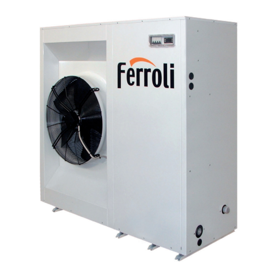
- Page 1 AIR-WATER CHILLERS AND HEAT PUMPS FOR OUTDOOR INSTALLATION INSTALLATION AND OPERATION MANUAL...
- Page 2 Dear Customer, Thank you for having purchased a FERROLI product. It is the result of many years of experiences and of particular research studies and has been made with top quality materials and advanced technologies. The CE mark guarantees that the products satisfy all the applicable European Directives.
-
Page 3: Table Of Contents
TABLE OF CONTENTS GENERAL FEATURES . . . . . . . . . . . . . . . . . . . . . . . . . . . . . . . . . . . . . . . . . . . . . . . . . . . . . . . . . . . . . . . . . . . . . . . . . . . . . . . . . . . . . .4 General specifications . -
Page 4: General Features
Maximum absorbed current Refrigerant type and charge weight Weight empty unit Sound pressure level at 1 metre IP protection level Maximum pressure - high pressure side Maximum pressure - low pressure side PED certification body Ferroli Spa Via Ritonda 78/A (VR) Italy... -
Page 5: Unit Description
GENERAL FEATURES Unit description This series of air-water chillers and heat pumps satisfies the co- that allows the units to operate with low outdoor temperatures in oling and heating requirements of residential plants of small and cooling and high outdoor temperature in heating and permits to medium size. -
Page 6: Description Of Components
GENERAL FEATURES Description of components External structure. Basement, supporting structure and lateral residuals that could be present in the circuit, high and low panels are made of galvanized and painted sheet-steel (colour pressure switches in order to assure the compressor to operate inside the permitted limits, 4 way reverse cycle valve RAL 7035) to guarantee good resistance to atmospheric agents. -
Page 7: Control System
GENERAL FEATURES Control system The unit is managed by a microprocessor controller to which, pump management through a wiring board, all the electrical loads and the control integrative electrical heaters management in heating mode devices are connected. The user interface is realized by a (2 step logic) display and four buttons that allow to view and, if necessary, compressor and pump operating hours recording... -
Page 8: Accessories And Optional Equipment
ACCESSORIES AND OPTIONAL EQUIPMENT Options Standard pump Allows the circulation of the water on the plant side. Allows the circulation of the water on the plant side and guarantees a higher avai- High head pump lable static head, suitable for high pressure drop plants. Allows the circulation of the water on the plant side with the possibility to set the Modulating pump rotational speed of the pump in order to get the requested flow rate without the... -
Page 9: Accessories
ACCESSORIES AND OPTIONAL EQUIPMENT Accessories Supplied accessories Allow to reduce the transmission to the unit support plane of the mechanical vibrations generated by the compressor Rubber vibration dampers and by the fans in their normal operating mode. Coil protection grille Protects the external surface of the finned coil.. -
Page 10: Technical Data And Performance - Base Version (Vb)
TECHNICAL DATA AND PERFORMANCE - BASE VERSION (VB) Technical data Frame 19 .1 22 .1 26 .1 30 .1 35 .1 40 .1 Model U.M. Power supply 400 - 3N - 50 400 - 3N - 50 400 - 3N - 50 400 - 3N - 50 400 - 3N - 50 400 - 3N - 50... -
Page 11: Net Nominal Performances - Base Setting Up (Ab) - Standard Plants - Eurovent Certified Data
TECHNICAL DATA AND PERFORMANCE - BASE VERSION (VB) NET NOMINAL performances - Base setting up (AB) - Standard plants - EUROVENT certified data Frame 19 .1 22 .1 26 .1 30 .1 35 .1 40 .1 Model U.M. Cooling A35W7 ( source : air in 35°C d.b. -
Page 12: Net Nominal Performances - Low Noise Setting Up (As) - Standard Plants - Eurovent Certified Data
TECHNICAL DATA AND PERFORMANCE - BASE VERSION (VB) NET NOMINAL performances - Low noise setting up (AS) - Standard plants - EUROVENT certified data Frame 19 .1 22 .1 26 .1 30 .1 35 .1 40 .1 Model U.M. Cooling A35W7 ( source : air in 35°C d.b. -
Page 13: Cooling Performances
TECHNICAL DATA AND PERFORMANCE - BASE VERSION (VB) COOLING performances The graphs allow to get the corrective factors to be applied to the nominal performances in order to obtain the real performances in the selected operating conditions. For the "Operation limits" of the unit refer to the section limits. The reference nominal condition is: A35W7 (source : air in 35°C d.b. -
Page 14: Heating Performances
TECHNICAL DATA AND PERFORMANCE - BASE VERSION (VB) HEATING performances The graphs allow to get the corrective factors to be applied to the nominal performances in order to obtain the real performances in the selected operating conditions. For the "Operation limits" of the unit refer to the section limits. The reference nominal condition is: A7W45 (source : air in 7°C d.b. -
Page 15: Br - Bp Unit
BR - BP UNIT Corrective factors Correction factors to apply to the basic version data. ETHYLENE GLYCOL Percentage Of glycol in mass / volume 20 / 18,1 Freezing point [°C] Produced water temperature CCPF - Cooling capacity 0,912 0,855 0,798 0,738 0,683 CCPA - Power input... -
Page 16: Noise Levels
NOISE LEVELS Base setting up (AB) Sound pressure level Sound power levels [dB] Sound power at 10 me- Model by octave bands [Hz] level at 1 metre at 5 metres tres 1000 2000 4000 8000 [dB] [dB(A)] [dB(A)] [dB(A)] [dB(A)] 19 .1 82,4 83,6... -
Page 17: Electrical Data
ELECTRICAL DATA Electrical data Frame 19 .1 22 .1 26 .1 30 .1 35 .1 40 .1 Model U.M. Unit Power supply 400-3N-50 400-3N-50 400-3N-50 400-3N-50 400-3N-50 400-3N-50 V-ph-Hz F.L.A. Maximum total current input 15,8 17,6 19,1 24,4 26,8 30,8 F.L.I. -
Page 18: Operating Limits
OPERATING LIMITS The table below lists the operating limits within which correct operation of the units is guaranteed, depending on the Version and Operating Mode available for each type of unit. Remember that in Heat Pump units, heat recovery only takes place during operation in the cooling mode. Thermal gradient of the water Limit value Minimum... -
Page 19: Water Pressure Drop
WATER PRESSURE DROP... -
Page 20: Working Head
WORKING HEAD... - Page 21 WORKING HEAD...
-
Page 22: Dimensional And Physical Data
DIMENSIONAL AND PHYSICAL DATA Overall dimensions Frame 19 .1 22 .1 26 .1 30 .1 35 .1 40 .1 Model Plant return 1"1/4 F 1"1/4 F 1"1/4 F 1"1/4 F 1"1/4 F 1"1/4 F Plant flow 1"1/4 M 1"1/4 M 1"1/4 M 1"1/4 M 1"1/4 M... -
Page 23: Weights
DIMENSIONAL AND PHYSICAL DATA Weights Frame 19 .1 22 .1 26 .1 30 .1 35 .1 40 .1 Model U.M. Empty weight Unit without options Standard pump High head pump Modulating pump Storing Tank and standard pump pumping module Tank and high head pump Tank and modulating pump... -
Page 24: Reception And Positioning
RECEPTION AND POSITIONING Receiving Check on receiving necessary for a corect handling during storing and installation. As soon as the unit is received verify accurately the correspon- The unit is supplied on a pallet suitable for the transport. It is dance of the load to what was ordered to make sure that all advisable to place protective material between the truck and the the material has been delivered. -
Page 25: Hydraulic Connections
HYDRAULIC CONNECTIONS General rules A mesh filter (hole Ø<0,5mm for plates heat exchanger) must be installed on the unit’s water inlet otherwise warranty is immediately for- feited . The filter performs the function of blocking any foreign matter in the system’s plumbing circuit (shavings, machining debris, etc .) limiting or avoiding possible problems of fouling (that decreases the heat exchange coefficient), erosion, and clogging The clogging and fouling of the exchanger can lead to a reduction of the water flow rate and . -
Page 26: Water Component For Corrosion Limit
HYDRAULIC CONNECTIONS Water component for corrosion limit To avoid corrosion problems in water exchangers make sure that the water used in the plant meets the requirements listed in the table. 7.5 ÷ 9.0 Free Chlorine < 0.5 Fe3+ < 0.5 SO4 -- <... -
Page 27: Electrical Connections
ELECTRICAL CONNECTIONS Electrical connections The electrical wirings must be carried out by qualified personnel Upstream protection according to the regulations in force at the installation time in the An automatic switch suitable for ensuring protection against country of installation. Before starting any work on the electrical overcurrents and indirect contacts must be installed upstream circuit make sure that the unit power supply line is disconnected each power supply line. -
Page 28: R410A Protection Devices
R410A PROTECTION DEVICES Protection devices HIGH PRESSURE LEVEL Device High pressure automatic switch Trip out (barg) 41.0 Trip in (barg) 29.5 connected to electronic controller effect stop the compressors and the fans of that circuit reset * YES by keyboard if the high pressure switch has trip-in and after the solution of the problem that generates the alarm *: For more details refers to section monitoring basic system. -
Page 29: Refrigerant Flow Diagram
REFRIGERANT FLOW DIAGRAM IR unit STAE R1 / RAG SL** TPL* VP + VA * : Optional / accessory ** : Do not installed if present TPL accessory DESCRIPTION DESCRIPTION finned coil Outlet pressure Capillary by-pass Plate heat exchanger compressor Probe inlet water filter dryer probe liquid... -
Page 30: Control System
CONTROL SYSTEM Control system The unit is managed by a microprocessor controller to which, through a wiring board, all the electrical loads and the control devices are connected. The user interface is reali- mode zed by a display and four buttons that allow to view and, if necessary, modify all the operating parameters of the unit. - Page 31 CONTROL SYSTEM Display Normally are shown : 88:8.8 • the setting temperature that is the water inlet temperature (in tenths of Celsius degree with decimal dot) • alarm code, if at least one alarm is active (if more alarms are active, the first one according to the order of the Alarm Table, is shown) In menu mode the informations on the display change according to the position inside the menu (see the structure of the menu).
-
Page 32: Menu Structure
CONTROL SYSTEM Menu structure The control system provides for three menus with tree structure. Menu Access procedure Sub menu Available functions Parameters Stby Operating Press ESC button for long Operating mode HEAT mode (ESC button associated function) change COOL Display input AI1 Ai01 Ai02 Display input AI2... -
Page 33: Inputs And Outputs
CONTROL SYSTEM Inputs and outputs In order to control the unit, the controller is equipped with the following inputs and outputs : • Analogue inputs : • Digital inputs : • Analogue outputs : • Digital outputs : DESCRIPTION CHARACTERISTICS Analogue inputs water inlet probe NTC (-30°C ÷... -
Page 34: Alarms
CONTROL SYSTEM Alarms Alarm activation and reset The controller can perform a complete diagnosis of the unit, detecting all the operating faults and reporting a set of alarms. Activation of an alarm involves : • locking of the loads concerned •... -
Page 35: Alarms Table
CONTROL SYSTEM Alarms table Locked loads CODE ALARM RESEt INPUT Low pressure Er05 Phase presence and sequence controller A / M Soft starter alarm Differential pressure switch A / M Er20 Antifreeze Er30 Er41 High pressure / Fan thermal protection A / M Er45 Clock fault... -
Page 36: Functions Available For The User
CONTROL SYSTEM Functions available for the user Operating mode selection It's possible to select the operating mode by accessing the “Operating mode” menu : Cooling COOL Heating HEAT STAND BY * StdBY * The antifreeze function is still active. Remote STAND BY This function allows remote selection of the STANDBY mode. -
Page 37: Serial Communication
CONTROL SYSTEM Serial communication The unit can communicate on a serial line using the Modbus communication protocol with RTU coding. The unit can be connected to an RS485 network by means of the serial interface supplied as an accessory, and reply to the requests of any master device connected to the network. -
Page 38: Probes Characteristics
CONTROL SYSTEM Register address Label Description number Set point cooling 16900 4204 °C COOL Set point heating 16902 4206 °C HEAT Remote stand by enable 49303 C097 CF19 Remote Cooling-Heating enable 49304 C098 CF20 Device serial address 49178 C01A CF63 Heat pump enable 49665 C201... -
Page 39: Inverter
INVERTER The display is accessible from the external of the unit dismounting the frontal panel of the electrical box. (ref. fig.1). The unit can be equipped with n° 1 for each pump (part. 1-fig.2) and/or with n° 1 for each fan (part. 2-fig.2). Fig.1 Fig.2 MODALITÀ... - Page 40 INVERTER Input on Code Alarm Cause Troubleshooting inverter 1. Ensure that the ambient temperature falls within the specified temperature range Heat sink 2. Make sure that the ventilation holes are not obstructed Overheating temperature too 3. Remove any foreign objects from the heatsinks and check for possible dirty heat sink fins high 4.
- Page 41 INVERTER Input on Code Alarm Cause Troubleshooting inverter Internal EEPROM Internal error Return to factory cF1.0 can not be programmed Internal EEPROM Internal error Return to factory cF1.1 can not be programmed Internal 1. Press RESET key to set all parameters to factory setting EEPROM can Internal error cF2.0...
-
Page 42: Start Up
START-UP START UP General Rules Start up The following operations must be carried out only by properly trained personnel. To make the contractual warranty effective, start up must be carried out by autho- rized service centres. Before calling the service centre it is advisable to make sure that all the installation steps have been completed (positioning, electrical connections, hydraulic connections). Preliminary Operations switches: close the shutoff valve at the outlet of the heat exchanger, the Preliminary operation... -
Page 43: Safety And Maintenance
SAFETY AND MAINTENANCE SAFETY AND MAINTENANCE Basic safety rules Basic safety rules Recall that the use of products that use electricity and water entails the observance of some basic safety rules , such as: This applian- ce is not intended for use by persons ( including children) with reduced physical , sensory or mental capabilities or lack of experience and knowledge, unless supervised or instructed on the use of the appliance by a person responsible for their safety . -
Page 44: General Recommendations About The R410A Refrigerant Used
SAFETY AND MAINTENANCE SAFETY AND MAINTENANCE General recommendations about the R410A refrigerant used General recommendations about the R410A refrigerant used 1 SUPPLIER COMPANY AND PRODUCT IDENTIFICATION Card No. FRIG 8 Product R-410A Supplier company identification RIVOIRA SpA 2 COMPOSITION / INFORMATION ON INGREDIENTS Substance / Preparation Preparation Components / Impurities... - Page 45 SAFETY AND MAINTENANCE SAFETY AND MAINTENANCE 13 CONSIDERATIONS ON DISPOSAL General Do not dispose of where accumulation can be hazardous. Usable with reconditioning. The depressurised containers must be returned to the supplier. Contact the supplier if instructions for use are deemed necessary. 14 INFORMATION FOR TRANSPORT Designation for transport LIQUEFIED GAS N.A.S.
-
Page 46: General Rules For Maintanance
SAFETY AND MAINTENANCE SAFETY AND MAINTENANCE General Rules for Maintanance General Rules for Maintanance The maintenance is extremely important for the functioning of the system and the regular working of the unit over time. In accordance with the European Regulation EC 303/2008 , it should be noted that companies and engineers in maintenance , repair, leak testing and recovery / recycle refrigerant gases should be CERTIFIED in accordance with local regulations. - Page 47 SAFETY AND MAINTENANCE SAFETY AND MAINTENANCE Axial fans Visually inspect these parts to make sure that the fans are well fixed to the bearing grille and that this latter is fixed to the structure of the unit. Check the fan bearings, and close the terminal box and cable glands. Bearings damaged and bad fixing are the source of abnormal noise and vibrations, •...
- Page 48 Ferroli spa ¬ 37047 San Bonifacio (Verona) Italy ¬ Via Ritonda 78/A tel. +39.045.6139411 ¬ fax +39.045.6100933 ¬ www.ferroli.it...
Need help?
Do you have a question about the RMA2 HE VB 19.1 and is the answer not in the manual?
Questions and answers