Table of Contents
Advertisement
Advertisement
Table of Contents

Subscribe to Our Youtube Channel
Related Manuals for CSZ BLANKETROL III 233


Summary of Contents for CSZ BLANKETROL III 233
- Page 1 Operation and Technical Manual Model 233 Hyper-Hypothermia Units Cincinnati Sub-Zero Products, Inc. • 12011 Mosteller Road • Cincinnati, Ohio 45241, U.S.A. www.cszmedical.com In Europe: • CEpartner4U • Esdoornlaan 13, 3951 DB Maarn. The Netherlands Manual 56201 Rev. A, ECN: M602-3259...
- Page 2 Symbol Definitions Read Operation Gradient Instructions and Manual Temperature Set Gradient 10˚ C Before Operating Variable Smart Automatic Manual Mode Control Monitor Control Only Patient Water Silence Temperature Temperature Alarm Test Indicators Inlet Low Water Water Flow Fill to Strainer Outlet Level Indicator...
- Page 3 Contamination can affect patient’s health, i.e. skin irritation/rash may result. • Use only YSI 400 Series, or equivalent, probes on CSZ equipment (refer to Figure (6-8.)). Failure to do this will cause incorrect temperature readings and may result in inadequate/inappropriate treatment.
- Page 4 WARNING • The repair, calibration, and servicing of the BLANKETROL III should be performed by qualified Medical Equipment Service Technicians, Certified Biomedical Electronics Technicians, or Certified Clinical Engineers familiar with good repair practices for servicing medical devices, and in accordance with instructions contained in this manual. Improper repair can result in damage to the BLANKETROL III system and patient injury.
-
Page 5: Table Of Contents
AUTHORIZED EUROPEAN REPRESENTATIVE:..................... 1 BEFORE YOU CALL FOR SERVICE........................1 IN-WARRANTY REPAIR AND PARTS....................... 1 RECEIVING INSPECTION ............................. 1 IMPORTANT SAFETY INFORMATION ......................1 SECTION 1. INTRODUCTION ..........................2 1-0. GENERAL SAFETY PRECAUTIONS ....................2 1-1. GENERAL DESCRIPTION OF THIS MANUAL................... 2 1-2. - Page 6 4-6. MAINTENANCE OF THE HYPER-HYPOTHERMIA BLANKETS ..........64 4.6.1 PLASTIPAD REUSABLE BLANKET................... 64 4-6.2. MAXI-THERM, AND MAXI-THERM LITE HYPER-HYPOTHERMIA BLANKETS ....65 4-7. MAINTENANCE OF REUSABLE THERMISTOR PROBES ............. 65 4-8. LOW LIMIT SAFETIES CHECK......................66 4-9. HIGH LIMIT SAFETIES CHECK......................67 4-10.
- Page 7 Figure 1-2. BLANKETROL III Unit - Right Side View ..................7 Figure 1-3. BLANKETROL III Unit - Rear View....................9 Figure 1-4.A. BLANKETROL III Unit – Membrane Control Panel..............11 Figure 1-4.B. BLANKETROL III Unit – Membrane Control Panel..............12 Figure 4-1. MAINTENANCE CHECK LIST ......................58 Figure 5-1.
-
Page 9: Authorized European Representative
TECHNICAL HELP United States and Canada Telephone 1-513-772-8810 Cincinnati Sub-Zero Products, Inc. Toll Free 1-800-989-7373 12011 Mosteller Road 1-513-772-9119 Cincinnati, OH 45241 Authorized European Representative: CEpartner4U Telephone +31 (0) 6-516.536.26 Esdoornlaan 13 3951 DB Maarn The Netherlands BEFORE YOU CALL FOR SERVICE... To help us better serve you, please have the serial number of your BLANKETROL III unit ready when you call for parts or service. -
Page 10: Section 1. Introduction
1-1. GENERAL DESCRIPTION OF THIS MANUAL This manual describes the operation, maintenance, and service of the CSZ BLANKETROL III hyper-hypothermia system. Section one describes the physical and functional characteristics of the BLANKETROL III System. Section two describes how to prepare the BLANKETROL III unit for general use. -
Page 11: General Description Of The Blanketrol Iii System
1-2. GENERAL DESCRIPTION OF THE BLANKETROL III SYSTEM The CSZ BLANKETROL III (Model 233) Hyper-Hypothermia System is used to lower or to raise a patient's temperature and/or maintain a desired patient temperature through conductive heat transfer. The CSZ BLANKETROL III unit is composed of a heater, a compressor, a circulating pump, and a microprocessor. -
Page 12: Physical Description Of The Blanketrol Iii Unit
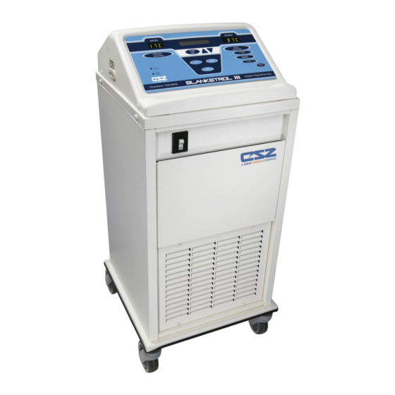
INTRODUCTION BLANKETROL III, Model 233 OPERATION AND TECHNICAL MANUAL intracranial pressure, to control cerebral edema, and to reduce oxygen requirements. This system is also used in the treatment of burns, shock, cardiac arrest, and gastrointestinal hemorrhage. 1-4. PHYSICAL DESCRIPTION OF THE BLANKETROL III UNIT See Section (7) for specifications and certifications of the BLANKETROL III. - Page 13 INTRODUCTION BLANKETROL III, Model 233 OPERATION AND TECHNICAL MANUAL FIGURE 1-1. BLANKETROL III, FRONT VIEW Manual 56201 Rev. A, ECN: M602-3259...
-
Page 14: 1-4.2. External Features - Right Side View
INTRODUCTION BLANKETROL III, Model 233 OPERATION AND TECHNICAL MANUAL 1-4.2. EXTERNAL FEATURES - RIGHT SIDE VIEW The external features in Figure (1-2.) of the BLANKETROL II unit are described as follows: The water flow indicator is a paddle wheel immersed in the path of the circulating water with a window to the outside. -
Page 15: Figure 1-2. Blanketrol Iii Unit - Right Side View
INTRODUCTION BLANKETROL III, Model 233 OPERATION AND TECHNICAL MANUAL FIGURE 1-2. BLANKETROL III, RIGHT SIDE VIEW Manual 56201 Rev. A, ECN: M602-3259... -
Page 16: 1-4.3. External Features - Rear View
INTRODUCTION BLANKETROL III, Model 233 OPERATION AND TECHNICAL MANUAL 1-4.3. EXTERNAL FEATURES - REAR VIEW The external features in Figure (1-3.) of the BLANKETROL III unit are described as follows: The specification label outlines the BLANKETROL III unit's electrical requirements. The maintenance label outlines the periodic checks for the BLANKETROL III unit. -
Page 17: Figure 1-3. Blanketrol Iii Unit - Rear View
INTRODUCTION BLANKETROL III, Model 233 OPERATION AND TECHNICAL MANUAL FIGURE 1-3. BLANKETROL III, REAR VIEW Manual 56201 Rev. A, ECN: M602-3259... -
Page 18: 1-4.4. Expanded Description Of The Blanketrol Iii Membrane Control Panel
INTRODUCTION BLANKETROL III, Model 233 OPERATION AND TECHNICAL MANUAL 1-4.4. EXPANDED DESCRIPTION OF THE BLANKETROL III MEMBRANE CONTROL PANEL The membrane control panel as shown in Figure (1-4.A.) for 115 Volt and (1-4.B) for 230 Volt is composed of pressure sensitive touch switches and LED displays. The membrane control panel is divided into the following sections: The green digital display labeled WATER shows the actual temperature of the circulating water. -
Page 19: Figure 1-4.A. Blanketrol Iii Unit - Membrane Control Panel
INTRODUCTION BLANKETROL III, Model 233 OPERATION AND TECHNICAL MANUAL The LOW WATER symbol indicates when the unit is low on water by flashing the red LED to the left of the symbol, sounding an audible alarm and displaying ”LOW WATER” in the status display. Refer to Section (3-12-D. Low Water). C/F button allows the operator to select the measurement scale, Celsius or Fahrenheit, by which the unit functions. -
Page 20: Required Accessories
INTRODUCTION BLANKETROL III, Model 233 OPERATION AND TECHNICAL MANUAL FIGURE 1-4.B. BLANKETROL III MEMBRANE CONTROL PANEL, 230 VAC UNITS 1-5. REQUIRED ACCESSORIES Operation of the BLANKETROL III unit requires the use of the blanket(s) designed to circulate warm or cool distilled water, a connecting hose with quick-disconnect male and female couplings and a 400 Series thermistor probe if any of the automatic modes are to be utilized. - Page 21 INTRODUCTION BLANKETROL III, Model 233 OPERATION AND TECHNICAL MANUAL this case, the patient's temperature must be closely monitored. There is no relationship between the temperature of the circulating fluid and the temperature of the patient. In the AUTO CONTROL MODE, the operator sets the desired temperature of the patient. In addition, the operator must attach a 400 Series probe in or to the patient.
-
Page 22: 1-6.2. Heating System
INTRODUCTION BLANKETROL III, Model 233 OPERATION AND TECHNICAL MANUAL the set point range, the unit resumes operation in GRADIENT VARIABLE SMART MODE with an initial gradient offset equal to the original value selected by the operator. In addition, the BLANKETROL III unit can be set to operate in MONITOR ONLY MODE. In this mode, the 400 Series probe is attached to or inserted into the patient and is connected to the unit. -
Page 23: 1-6.5. Temperature Safety Control System
INTRODUCTION BLANKETROL III, Model 233 OPERATION AND TECHNICAL MANUAL The circulating water flows over and around the heating/cooling element located in the circulating reservoir. The heated or cooled water then flows out the reservoir to the circulating pump, through the pump housing, through connecting hoses over a water temperature sensor to the hyper- hypothermia blanket(s). -
Page 24: 1-6.6 Usb Port Operation
INTRODUCTION BLANKETROL III, Model 233 OPERATION AND TECHNICAL MANUAL If software fails and circulating water reaches 44.0°C ± 2°C (111.2°F ± 3.6°F), the back-up safety device shuts off the unit, status display flashes HIGH LIMIT REMOVE FROM SERVICE, and the trouble alarm sounds. -
Page 25: Section 2. General Preparation Of The Blanketrol Iii System
OPERATION BLANKETROL III, Model 233 OPERATION AND TECHNICAL MANUAL SECTION 2. GENERAL PREPARATION OF THE BLANKETROL III SYSTEM 2-1. INTRODUCTION This section describes the procedures to prepare the BLANKETROL III unit for general use. This entails unpacking the shipment, arranging all the equipment for the first time, and completing a test routine. -
Page 26: 2-3.1. Inspecting And Arranging The Equipment
OPERATION BLANKETROL III, Model 233 OPERATION AND TECHNICAL MANUAL 2-3.1. INSPECTING AND ARRANGING THE EQUIPMENT Place the BLANKETROL III unit in an uncluttered work space that is accessible to the correct power source with an ambient temperature between 15°C – 30°C (59°F – 86°F). -
Page 27: 2-3.2. Completing A System Test Routine
OPERATION BLANKETROL III, Model 233 OPERATION AND TECHNICAL MANUAL Check that the power switch of the unit is in “O” position (unit is off). WARNING • Do not by-pass ground lug. Electrical hazards may result. Insert the plug into a properly grounded hospital grade receptacle. 2-3.2. - Page 28 OPERATION BLANKETROL III, Model 233 OPERATION AND TECHNICAL MANUAL Press the MONITOR ONLY button. 1. The LED in the corner of the MONITOR ONLY switch lights up 2. An alarm sounds. 3. The status displays CHECK PROBE because no probe is attached. Press the TEMP SET switch.
- Page 29 OPERATION BLANKETROL III, Model 233 OPERATION AND TECHNICAL MANUAL WARNING • Water leaks present a risk of infection to the patient and should be handled accordingly. Proper sanitation procedures should be followed including, but not limited to, the preventative maintenance described in this manual. Leaky blankets or hoses should never be used.
- Page 30 OPERATION BLANKETROL III, Model 233 OPERATION AND TECHNICAL MANUAL CAUTION • Handling or use of the patient probe may result in damage from electrostatic discharge (ESD) if proper precautions are not taken. Insert a 400 Series probe into the jack on the side of the unit. Press the AUTO CONTROL button.
- Page 31 OPERATION BLANKETROL III, Model 233 OPERATION AND TECHNICAL MANUAL Press the AUTO CONTROL button. The microprocessor board beeps. The LED in the corner of the button lights up. The WATER display shows the temperature of the water in the reservoir. The status display shows: XXXXXX PATIENT AUTO...
- Page 32 OPERATION BLANKETROL III, Model 233 OPERATION AND TECHNICAL MANUAL The microprocessor board beeps. The LED in the corner of the button lights up. The Status display returns to set temperature mode. Press GRADIENT 10C button and then SMART button The microprocessor board beeps. The LED in the corner of the buttons light up.
- Page 33 OPERATION BLANKETROL III, Model 233 OPERATION AND TECHNICAL MANUAL The status display shows either: XXXXXX PATIENT AUTO SETPT 37.0 C Or status display shows: PATIENT @SETPT AUTO SETPT 37.0 C XXXXXX is HEATING, or COOLING. The above depends upon the relationship of the blanket water temperature to the set point temperature.
-
Page 34: Unit And Patient Related Precautions
OPERATION BLANKETROL III, Model 233 OPERATION AND TECHNICAL MANUAL The LED in the corner of the button lights up. The Status display returns to set temperature mode. To complete this test routine, turn the power switch off. The membrane control panel goes blank. The green light of the power switch goes out. -
Page 35: Patient Preparation And Bedside Care
If using a vinyl blanket, place a dry absorbent sheet between the patient and the blanket to prevent moisture from accumulating. • Use only 400 Series, or equivalent, probes on CSZ equipment. Failure to do this will cause incorrect temperature readings. •... - Page 36 OPERATION BLANKETROL III, Model 233 OPERATION AND TECHNICAL MANUAL WARNING • Power interruption will cause the BLANKETROL III to revert to CHECK SET POINT resulting in no therapy to the patient. Follow instructions for desired mode to resume operation. Failure to resume therapy could result in serious injury or death. •...
- Page 37 OPERATION BLANKETROL III, Model 233 OPERATION AND TECHNICAL MANUAL Standard nursing procedures while using a hyper-hypothermia blanket include the following tasks: Patient's vital signs should be recorded and evaluated frequently. Operating room, temperature sensitive and pediatric patients may deviate from normal responses to external applications of heat and cold.
-
Page 38: Section 3. Operating The Blanketrol Iii Unit
OPERATION BLANKETROL III, Model 233 OPERATION AND TECHNICAL MANUAL SECTION 3. OPERATING THE BLANKETROL III UNIT 3-1. INTRODUCTION This section describes how to operate the BLANKETROL III unit in order to control a patient's temperature. First, collect the equipment and prepare the patient. Second, decide which mode of operation to use. - Page 39 OPERATION BLANKETROL III, Model 233 OPERATION AND TECHNICAL MANUAL sounds and the Status display flashes LOW WATER. The operator cannot proceed until this is corrected as described in Sections (3-12-D.) and (4-2.2). Check that the power switch is in the “O” position (unit is off). Inspect the power plug for bent or missing prongs.
- Page 40 OPERATION BLANKETROL III, Model 233 OPERATION AND TECHNICAL MANUAL If the patient's temperature is to be monitored as required in an automatic control mode or MONITOR ONLY MODE, insert or attach a 400 Series probe in or on the patient. A rectal probe is inserted into the rectum and secured with tape to the leg of the patient.
-
Page 41: Operating The Blanketrol Iii Unit In Auto Control Mode
OPERATION BLANKETROL III, Model 233 OPERATION AND TECHNICAL MANUAL 3-3. OPERATING THE BLANKETROL III UNIT IN AUTO CONTROL MODE WARNING • A physician's order is required for setting blanket temperature and use of equipment. At least every 20 minutes, or as directed by physician, check patient's temperature and skin condition of areas in contact with blanket;... - Page 42 OPERATION BLANKETROL III, Model 233 OPERATION AND TECHNICAL MANUAL The microprocessor board beeps. The set point on the status display changes. Press the AUTO CONTROL button. The microprocessor board beeps. The LED in the corner of the button lights up. The Patient display shows the patient's actual temperature.
-
Page 43: Operating The Blanketrol Iii Unit In Manual Control Mode
OPERATION BLANKETROL III, Model 233 OPERATION AND TECHNICAL MANUAL NOTE: IN ORDER TO CHANGE FROM ANY CONTROL MODE TO ANOTHER CONTROL MODE, FIRST PRESS THE TEMP SET BUTTON AND THEN PROCEED TO THE DESIRED CONTROL MODE. In order to change from AUTOMATIC CONTROL MODE to MONITOR ONLY MODE, simply press the MONITOR ONLY button. - Page 44 OPERATION BLANKETROL III, Model 233 OPERATION AND TECHNICAL MANUAL Use the C/F button to choose the desired temperature scale. Press the Up arrow or Down arrow to change the SETPOINT display to the desired Blanket/Water set point temperature. As a safety precaution, the Blanket/Water temperature can only be set between 4°C - 42°C (39.2°F - 107.6°F).
-
Page 45: Operating The Blanketrol Iii Unit In Manual Control Mode With The Addition Of The Patient Probe
OPERATION BLANKETROL III, Model 233 OPERATION AND TECHNICAL MANUAL If at any time the status display shows a message other than the messages described in MANUAL CONTROL MODE procedures, make the changes indicated by the display and/or consult the list of display messages in Section (3-12.). -
Page 46: Operating The Blanketrol Iii Unit In Gradient 10C Mode
OPERATION BLANKETROL III, Model 233 OPERATION AND TECHNICAL MANUAL If at any time the status display shows a message other than the messages described in MANUAL CONTROL MODE procedures, make the changes indicated by the display and/or consult the list of display messages in Section (3-12.). - Page 47 OPERATION BLANKETROL III, Model 233 OPERATION AND TECHNICAL MANUAL Consult the physician's orders to determine the desired patient temperature. As a safety precaution, the desired patient set point can only be set between 30°C - 40°C (86°F - 104°F) to operate in GRADIENT 10C mode. Use the C/F button to choose the desired temperature scale.
-
Page 48: Operating The Blanketrol Iii Unit In Gradient 10C Smart Mode
OPERATION BLANKETROL III, Model 233 OPERATION AND TECHNICAL MANUAL To make any changes in the control settings, press the TEMP SET switch and begin again. The BLANKETROL III is now operating in GRADIENT 10C MODE. You should continue to monitor the unit and the patient. - Page 49 OPERATION BLANKETROL III, Model 233 OPERATION AND TECHNICAL MANUAL Press the power switch to “I” position. The switch lights up green. The microprocessor board goes through self test. The Status display flashes CHECK SETPT. Consult the physician's orders to determine the desired patient temperature. As a safety precaution, the desired patient set point can only be set between 30°C - 40°C (86°F - 104°F) to operate in GRADIENT 10C MODE.
-
Page 50: Operating The Blanketrol Iii Unit In Gradient Variable Mode
OPERATION BLANKETROL III, Model 233 OPERATION AND TECHNICAL MANUAL The pump is activated. The heater or compressor may also be activated. The water flow indicator on the right side panel begins to move. The water moves from the unit to the blanket and returns to the unit. Press the SMART key. - Page 51 OPERATION BLANKETROL III, Model 233 OPERATION AND TECHNICAL MANUAL The BLANKETROL III unit can be set to gradually affect a patient’s temperature by maintaining the circulating water temperature at a specific gradient from the patient’s body temperature. To do so, set the desired patient temperature in Celsius or Fahrenheit (115 Volt only), insert or attach the 400 Series probe in or on the patient and depress the GRADIENT VARIABLE button.
- Page 52 OPERATION BLANKETROL III, Model 233 OPERATION AND TECHNICAL MANUAL Press the Up arrow or Down arrow to change the gradient variable offset to the desired value. The microprocessor board beeps. The set point temperature in the status display changes. Press the GRADIENT VARIABLE button. The microprocessor board beeps.
-
Page 53: Operating The Blanketrol Iii Unit In Gradient Variable Smart Mode
OPERATION BLANKETROL III, Model 233 OPERATION AND TECHNICAL MANUAL NOTE: IN ORDER TO CHANGE FROM GRADIENT VARIABLE MODE TO ANOTHER CONTROL MODE, FIRST PRESS THE TEMP SET BUTTON AND THEN PROCEED TO THE DESIRED CONTROL MODE. In order to change from GRADIENT VARIABLE MODE to MONITOR ONLY MODE, simply press the MONITOR ONLY button. - Page 54 OPERATION BLANKETROL III, Model 233 OPERATION AND TECHNICAL MANUAL Use the C/F button to choose the desired temperature scale. Press the TEMP SET button. The microprocessor board beeps. The LED in the corner of the switch lights up. The status display shows a temperature set point. Press the Up arrow or Down arrow to change the set point temperature on the status display to the desired patient temperature.
-
Page 55: Operating The Blanketrol Iii Unit In Monitor Only Mode
OPERATION BLANKETROL III, Model 233 OPERATION AND TECHNICAL MANUAL The above depends upon the relationship of the blanket water temperature to the set point temperature. Note that the set point may be displayed in Fahrenheit if the operator is in Fahrenheit mode. The pump is activated. -
Page 56: Concluding Hyper-Hypothermia Treatment
OPERATION BLANKETROL III, Model 233 OPERATION AND TECHNICAL MANUAL Insert the probe into the probe jack on the right side of the unit. Press the power switch to “I” position. The switch lights up green. The microprocessor board goes through self-test. The status display flashes CHECK SETPT. -
Page 57: Status Display Messages
OPERATION BLANKETROL III, Model 233 OPERATION AND TECHNICAL MANUAL Permit the blanket(s) and hose to remain connected to the unit for about ten minutes. This allows some of the water to drain back into the unit. Remove the probe from the patient and probe jack. Maintenance of the REUSABLE probe is described in Section (4-7.). - Page 58 OPERATION BLANKETROL III, Model 233 OPERATION AND TECHNICAL MANUAL This message is displayed on the top line when the water temperature has WATER @SETPT reached the water temperature set point. During normal operation in the five automatic modes, AUTOMATIC CONTROL MODE, GRADIENT 10C MODE, GRADIENT 10C SMART MODE, GRADIENT VARIABLE MODE, and GRADIENT VARIABLE SMART MODE, the status display shows the following messages:...
- Page 59 The unit cannot be used again until it is serviced. The seven- segment displays (“WATER” and ”PATIENT”) will both be blank during this condition. Contact CSZ Technical Service. Manual 56201 Rev. A, ECN: M602-3259...
- Page 60 “EE01” “REMOVE FROM SERVICE” will reappear in the status display and the trouble alarm will sound. The unit cannot be used again until it is serviced. Contact CSZ Technical Service. Manual 56201 Rev. A, ECN: M602-3259...
- Page 61 This message will also be displayed if the WATER temperature is out of the range, 0°C – 52.0°C (32°F - 125.6°F), of the available temperature readout. Contact CSZ Technical Service. This message is displayed to alert the operator when the probe needs to be checked.
- Page 62 OPERATION BLANKETROL III, Model 233 OPERATION AND TECHNICAL MANUAL While in any of the five automatic modes, if the patient probe indicates only a direct short in the probe circuit this message occurs. As this message is displayed, the trouble alarm sounds and the unit shuts down. This alarm can be silenced using the SILENCE ALARM button.
- Page 63 OPERATION BLANKETROL III, Model 233 OPERATION AND TECHNICAL MANUAL This message displays the total hours of operation. To display this TOTAL HOURS message, simultaneously press the Increment and Decrement buttons. This message displays the total number of hours of operation until the next required PM.
-
Page 64: Section 4. General Maintenance Of The Blanketrol Iii System
MAINTENANCE BLANKETROL III, Model 233 OPERATION AND TECHNICAL MANUAL SECTION 4. GENERAL MAINTENANCE OF THE BLANKETROL III SYSTEM 4-1. INTRODUCTION This section describes the general requirements maintenance personnel should complete on a regular basis so that the BLANKETROL III System continues to operate within the manufacturers’ allowable tolerances. -
Page 65: 4-1.1. Test Equipment Required
The following test equipment is required to perform the preventive maintenance/functional check-out procedures: • CSZ's model TFRW 86171 Trimatic (Temperature Tester, Flow Meter, Resistance Tester) - Need Probe Extension Cable #TM-4A (Part # 39005) - Need Hose Assembly #TM-6 (Part # 91802) •... -
Page 66: Figure 4-1. Maintenance Checklist
MAINTENANCE BLANKETROL III, Model 233 OPERATION AND TECHNICAL MANUAL SUGGESTED PREVENTIVE MAINTENANCE CHECKLIST (Quarterly or when indicated by 500 hour PM notification) BLANKETROL III - Model 233 Hospital Control No. Serial Number Check When Completed External cabinet in good condition. (No unusual dents or missing parts) All labels properly affixed. -
Page 67: Maintenance Of The Water Reservoir
MAINTENANCE BLANKETROL III, Model 233 OPERATION AND TECHNICAL MANUAL 4-2. MAINTENANCE OF THE WATER RESERVOIR The dual compartment reservoir holds approximately 2 gallons (7.5 liters) of distilled water that remains in the unit between periods of use. Quarterly, the water reservoir should be drained and replenished. - Page 68 CSZ equipment. For this reason, all CSZ equipment have a suggested quarterly schedule for flushing and cleaning the water system in an effort to inhibit the growth of bacteria and fungi.
-
Page 69: 4-2.1. Draining The Reservoir
MAINTENANCE BLANKETROL III, Model 233 OPERATION AND TECHNICAL MANUAL Once no bleach is detected, add the appropriate amount of U.S.P. Grade Propylene Glycol to the water reservoir per the following chart: UNIT U.S.P. GRADE PROPYLENE GLYCOL PER UNIT Blanketrol III 16 ounces (500 cc) Continue to fill the water reservoir with distilled water. -
Page 70: 4-2.2. Replenishing The Reservoir
MAINTENANCE BLANKETROL III, Model 233 OPERATION AND TECHNICAL MANUAL The water is pumped into the container until there is approximately ½ gallon (1.9 liters) of water remaining to be drained. The status display flashes LOW WATER and the alarm sounds. The unit shuts down but the water continues to drain into the container because of gravitational pull. -
Page 71: Maintenance Of The Condenser And Grill
MAINTENANCE BLANKETROL III, Model 233 OPERATION AND TECHNICAL MANUAL Quarterly, or more often if deemed necessary, the water filter should be disassembled and cleaned. To do so, the reservoir must first be drained and the rear enclosure panel removed. The cap of the water filter assembly is unscrewed. -
Page 72: Maintenance Of The Blanketrol Iii Exterior - Cleaning Instructions
MAINTENANCE BLANKETROL III, Model 233 OPERATION AND TECHNICAL MANUAL WARNING • The repair, calibration, and servicing of the BLANKETROL III should be performed by qualified Medical Equipment Service Technicians, Certified Biomedical Electronics Technicians, or Certified Clinical Engineers familiar with good repair practices for servicing medical devices, and in accordance with instructions contained in this manual. -
Page 73: 4-6.2. Maxi-Therm, And Maxi-Therm Lite Hyper-Hypothermia Blankets
Reattach the male and female fittings onto the hoses. PLASTIPAD blankets can be patch repaired if the blanket is punctured and begins to leak. A PLASTIPAD Patch Kit with instructions is available at no charge upon request. Contact CSZ for Patch Kit information. -
Page 74: Low Limit Safeties Check
MAINTENANCE BLANKETROL III, Model 233 OPERATION AND TECHNICAL MANUAL 4-8. LOW LIMIT SAFETIES CHECK WARNING • The repair, calibration, and servicing of the BLANKETROL III should be performed by qualified Medical Equipment Service Technicians, Certified Biomedical Electronics Technicians, or Certified Clinical Engineers familiar with good repair practices for servicing medical devices, and in accordance with instructions contained in this manual. -
Page 75: High Limit Safeties Check
MAINTENANCE BLANKETROL III, Model 233 OPERATION AND TECHNICAL MANUAL 4-9. HIGH LIMIT SAFETIES CHECK WARNING • The repair, calibration, and servicing of the BLANKETROL III should be performed by qualified Medical Equipment Service Technicians, Certified Biomedical Electronics Technicians, or Certified Clinical Engineers familiar with good repair practices for servicing medical devices, and in accordance with instructions contained in this manual. -
Page 76: Temperature Accuracy Check
Press SILENCE ALARM button, TEMP SET button and increment button simultaneously to reset the alarm. 4-10. TEMPERATURE ACCURACY CHECK For temperature accuracy and verification we recommend using the CSZ TFRW 86171 Trimatic. Follow directions enclosed in the Trimatic to test temperature accuracy. Manual 56201 Rev. A, ECN: M602-3259... -
Page 77: Section 5. Field Repair/Service Of The Blanketrol Iii Unit
FIELD REPAIR/SERVICE BLANKETROL III, Model 233 OPERATION AND TECHNICAL MANUAL SECTION 5. FIELD REPAIR/SERVICE OF THE BLANKETROL III UNIT WARNING • Always unplug the unit before accessing internal components during service. Failure to unplug the unit could result in electric shock. •... - Page 78 FIELD REPAIR/SERVICE BLANKETROL III, Model 233 OPERATION AND TECHNICAL MANUAL A. Upper manifold (return) B. Water temperature sensor C. Lower manifold (outlet) D. Pump housing assembly E. Transformer F. Compressor G. Compressor electrical box H. Filter drier Refrigeration solenoid valve J.
-
Page 79: Figure 5-1. Blanketrol Iii Unit - Exposed Rear View
FIELD REPAIR/SERVICE BLANKETROL III, Model 233 OPERATION AND TECHNICAL MANUAL FIGURE 5-1. BLANKETROL III EXPOSED REAR VIEW Manual 56201 Rev. A, ECN: M602-3259... -
Page 80: Access To The Interior Of The Blanketrol Iii Unit
FIELD REPAIR/SERVICE BLANKETROL III, Model 233 OPERATION AND TECHNICAL MANUAL 5-2. ACCESS TO THE INTERIOR OF THE BLANKETROL III UNIT All internal operating components are readily accessible by removing the rear enclosure panel, removing the top of the unit, or extending the front storage drawer. NOTE: DRAIN THE RESERVOIR AND DISCONNECT THE POWER CORD FROM THE POWER SOURCE BEFORE REMOVING ANY PART FROM THE UNIT. -
Page 81: 5-2.4. Disconnecting The Cables From The Microprocessor Board
FIELD REPAIR/SERVICE BLANKETROL III, Model 233 OPERATION AND TECHNICAL MANUAL Remove the four Phillips screws. Carefully lift up the front edge of the top of the unit so that you can see the stainless steel divider reservoir cover. The microprocessor board is attached to the top assembly. -
Page 82: 5-2.5. Extending The Front Storage Drawer
FIELD REPAIR/SERVICE BLANKETROL III, Model 233 OPERATION AND TECHNICAL MANUAL Remove the 4 power supply wires by loosening the screws that tighten the wires in place. The top of the unit may now be removed from the base. 5-2.5. EXTENDING THE FRONT STORAGE DRAWER WARNING •... -
Page 83: Replacement Of The Water Filter Assembly
FIELD REPAIR/SERVICE BLANKETROL III, Model 233 OPERATION AND TECHNICAL MANUAL Remove the rear enclosure panel as described in Section (5-2.1.). Locate the heater inserted in the center of the reservoir plate and the lead wires that go to the electrical box, as shown in Figure (5-1-Q). Fiberglass tubing covers the lead wires. -
Page 84: Replacement Of The Pump Housing
FIELD REPAIR/SERVICE BLANKETROL III, Model 233 OPERATION AND TECHNICAL MANUAL Insert the replacement water filter assembly so the cap and screen point down and the arrow on the top points to the right. Connect one end to the hose from the water flow indicator and the other end of the hose to the reservoir. -
Page 85: Replacement Of The Pump Motor
FIELD REPAIR/SERVICE BLANKETROL III, Model 233 OPERATION AND TECHNICAL MANUAL Reconnect the hose of the water manifold to the outlet at the top of the pump housing and tighten the screw clamp. Reconnect the hose of the water reservoir to the inlet at the center of the pump housing and tighten the screw clamp. - Page 86 FIELD REPAIR/SERVICE BLANKETROL III, Model 233 OPERATION AND TECHNICAL MANUAL Trace the three-wire cable from the pump motor to the electrical box. The cable enters the box from the right side. Locate the termination of the three wires. Reference the wiring diagram located on the electrical box.
-
Page 87: Replacement Of The Flow Switch
FIELD REPAIR/SERVICE BLANKETROL III, Model 233 OPERATION AND TECHNICAL MANUAL 5-7. REPLACEMENT OF THE FLOW SWITCH WARNING • Always unplug the unit before accessing internal components during service. Failure to unplug the unit could result in electric shock. CAUTION • Always drain the BLANKETROL III to a sanitary drain because bio-contaminants may be present in the unit’s water supply. -
Page 88: Replacement Of The Water Temperature Sensor
FIELD REPAIR/SERVICE BLANKETROL III, Model 233 OPERATION AND TECHNICAL MANUAL 5-8. REPLACEMENT OF THE WATER TEMPERATURE SENSOR WARNING • Always unplug the unit before accessing internal components during service. Failure to unplug the unit could result in electric shock. Obtain replacement water temperature sensor. CAUTION •... - Page 89 FIELD REPAIR/SERVICE BLANKETROL III, Model 233 OPERATION AND TECHNICAL MANUAL Remove the rear enclosure panel as described in Section (5-2.2.). Locate the copper water manifold to be replaced. The two manifolds, one lower and one upper, are wrapped in black foam and are secured to the left side (viewed from the rear) of the unit as shown in Figure (5-1-A &...
-
Page 90: Replacement Of The Compressor Starting Capacitor, The Overload Protector, And/Or The Compressor Relay
Replace the rear enclosure panel as described in Section (5-2.2.). 5-10. REPLACEMENT OF THE COMPRESSOR STARTING CAPACITOR, THE OVERLOAD PROTECTOR, AND/OR THE COMPRESSOR RELAY NOTE: For replacement of these parts call CSZ Technical Service. 5-11. REPLACEMENT OF THE THERMAL DISC OVER TEMPERATURE DEVICE WARNING •... -
Page 91: Replacement Or Cleaning Of The Water Flow Indicator Assembly
FIELD REPAIR/SERVICE BLANKETROL III, Model 233 OPERATION AND TECHNICAL MANUAL Using a Phillips screwdriver remove the two screws at the top and bottom of the thermal disc. Remove the thermal disc. Install the replacement thermal disc. Replace and tighten the two screws. Insert the slide-on connector to the insulated terminal (white wire) and (orange wire) of the thermal disc. -
Page 92: Replacement Of The On/Off Power Switch
FIELD REPAIR/SERVICE BLANKETROL III, Model 233 OPERATION AND TECHNICAL MANUAL Remove the four remaining Phillips head screws around the face of the water flow indicator. Set the screws to the side. Disassemble the parts of the water flow indicator. Do not lose the large black O-ring. Rinse thoroughly with clean water. -
Page 93: Replacement Of The Water Level Sensor Assembly
FIELD REPAIR/SERVICE BLANKETROL III, Model 233 OPERATION AND TECHNICAL MANUAL Position the replacement power switch into the unit so that the labels are upright and “I” is at the top. Connect the wires in the same locations in which they were disconnected. Work the power switch and attached cable to the inside of the unit by pressing together the tension clips on the top and bottom of the switch assembly. -
Page 94: Replacement Of The Microprocessor Board And/Or The Membrane Control Panel
FIELD REPAIR/SERVICE BLANKETROL III, Model 233 OPERATION AND TECHNICAL MANUAL Refill the reservoir as described in Section (4-2.2.). 5-15. REPLACEMENT OF THE MICROPROCESSOR BOARD AND/OR THE MEMBRANE CONTROL PANEL WARNING • Always unplug the unit before accessing internal components during service. Failure to unplug the unit could result in electric shock. -
Page 95: Leakage Current
FIELD REPAIR/SERVICE BLANKETROL III, Model 233 OPERATION AND TECHNICAL MANUAL Connect the membrane ribbon cable to the 11-pin connector at J7 position on microprocessor board. NOTE: BE CAREFUL NOT TO OVERTIGHTEN NUTS. Replace the nylon nuts; tighten the nuts. Reposition the top on the unit and reconnect the cables by referencing Section (5- 2.3. -
Page 96: 5-16.3 Taking Measurements In Reverse Polarity
FIELD REPAIR/SERVICE BLANKETROL III, Model 233 OPERATION AND TECHNICAL MANUAL Press the Down arrow so the set point is a low number. Press the MANUAL CONTROL button. The status display must show COOLING. Set the BLANKETROL III unit so that it is HEATING and record the Leakage Current. To set the unit in the heating cycle: Press the power switch to the “I”... -
Page 97: Troubleshooting Guide
FIELD REPAIR/SERVICE BLANKETROL III, Model 233 OPERATION AND TECHNICAL MANUAL TROUBLESHOOTING GUIDE 5-18. TROUBLESHOOTING GUIDE OBSERVATION POSSIBLE ACTION TO BE TAKEN PROBLEM Check that the power cord is A. The power switch of the plugged into a properly BLANKETROL III unit is Unit is unplugged grounded hospital grade set on, in “I”... - Page 98 FIELD REPAIR/SERVICE BLANKETROL III, Model 233 OPERATION AND TECHNICAL MANUAL TROUBLESHOOTING GUIDE OBSERVATION POSSIBLE ACTION TO BE TAKEN PROBLEM E. Unit is on, any switch on the membrane control panel is pressed but does not stay set, or when the Membrane switch has Replace membrane control operating mode is...
- Page 99 FIELD REPAIR/SERVICE BLANKETROL III, Model 233 OPERATION AND TECHNICAL MANUAL TROUBLESHOOTING GUIDE OBSERVATION POSSIBLE ACTION TO BE TAKEN PROBLEM Cable from the probe jack to microprocessor Reconnect cable (J8 board is disconnected, position on microprocessor status display flashes board). CHECK PROBE and the alarm sounds.
- Page 100 FIELD REPAIR/SERVICE BLANKETROL III, Model 233 OPERATION AND TECHNICAL MANUAL TROUBLESHOOTING GUIDE OBSERVATION POSSIBLE ACTION TO BE TAKEN PROBLEM Other than a 400 Series probe was inserted in Replace with the correct 400 the probe jack. Series probe (refer to Figure (6-8.)).
- Page 101 FIELD REPAIR/SERVICE BLANKETROL III, Model 233 OPERATION AND TECHNICAL MANUAL TROUBLESHOOTING GUIDE OBSERVATION POSSIBLE ACTION TO BE TAKEN PROBLEM N. The unit is operating in one of the three modes, Check line voltage. Reset set the unit momentarily Low line voltage or power point display and resume blanks and then the source.
- Page 102 FIELD REPAIR/SERVICE BLANKETROL III, Model 233 OPERATION AND TECHNICAL MANUAL TROUBLESHOOTING GUIDE OBSERVATION POSSIBLE ACTION TO BE TAKEN PROBLEM The Snap Disc high limit safety device is triggered which shuts Replace microprocessor Q. Unit is operating in down the unit when the board.
- Page 103 FIELD REPAIR/SERVICE BLANKETROL III, Model 233 OPERATION AND TECHNICAL MANUAL TROUBLESHOOTING GUIDE OBSERVATION POSSIBLE ACTION TO BE TAKEN PROBLEM Correctly set buttons. See Operator error; buttons Section (3.). not set correctly. Defective pump. Replace the pump. Check all couplings for Disengaged quick proper fit.
- Page 104 FIELD REPAIR/SERVICE BLANKETROL III, Model 233 OPERATION AND TECHNICAL MANUAL TROUBLESHOOTING GUIDE OBSERVATION POSSIBLE ACTION TO BE TAKEN PROBLEM Check for voltage compressor: a. If line voltage is present. U. Cont’d Compressor not running b. If line voltage is not present: Replace micro- processor board.
-
Page 105: Section 6. Parts Information
Section (6-3.) outlines the recommended replacement parts inventory. It is strongly recommended that all parts be replaced with parts purchased from CSZ or CSZ International GmbH. Use of other parts could void the warranty on the unit and possibly damage the unit. -
Page 106: Returning Parts Under Warranty
PARTS INFORMATION BLANKETROL III, Model 233 OPERATION AND TECHNICAL MANUAL 6-4. RETURNING PARTS UNDER WARRANTY All parts are covered by a two (2) year warranty. To replace parts during the warranty period*, send the part prepaid to: Cincinnati Sub-Zero Products, Inc. 12011 Mosteller Road Cincinnati, Ohio 45241 Tel: (513) 772-8810... -
Page 107: Figure 6-1. Parts List A
PARTS INFORMATION BLANKETROL III, Model 233 OPERATION AND TECHNICAL MANUAL INTERNAL EXPLODED - FRONT VIEW Index # I.D. # Description 52242 White Reservoir Lid. 65177 Probe Jack Assembly 29008 USB Cable 56409 Membrane Control Panel (115V) 56408 Membrane Control Panel (230V) 91154 Top Assembly (115V) 91155... -
Page 108: Figure 6-2. Blanketrol Iii Unit - Internal Exploded Front View
PARTS INFORMATION BLANKETROL III, Model 233 OPERATION AND TECHNICAL MANUAL FIGURE 6-2. BLANKETROL III INTERNAL EXPLODED - FRONT VIEW Manual 56201 Rev. A, ECN: M602-3259... -
Page 109: Figure 6-3. Parts List B
PARTS INFORMATION BLANKETROL III, Model 233 OPERATION AND TECHNICAL MANUAL INTERNAL EXPLODED - REAR VIEW Index # I.D. # Description 91154 Top Assembly (115V) 91155 Top Assembly (230V) 56911 Patient Probe Label 60150 Screw 50095 Snap Cap 50149 Overflow Drain Hose Barb 60201 Drawer Stop - 8-32 x 1/2 60401... -
Page 110: Figure 6-4. Blanketrol Iii Unit - Internal Exploded Rear View
PARTS INFORMATION BLANKETROL III, Model 233 OPERATION AND TECHNICAL MANUAL FIGURE 6-4. BLANKETROL III INTERNAL EXPLODED - REAR VIEW Manual 56201 Rev. A, ECN: M602-3259... -
Page 111: Figure 6-5.A. Electrical Wiring Diagram - 115V
PARTS INFORMATION BLANKETROL III, Model 233 OPERATION AND TECHNICAL MANUAL FIGURE 6-5.A. BLANKETROL III ELECTRICAL WIRING DIAGRAM 115 VOLT Manual 56201 Rev. A, ECN: M602-3259... -
Page 112: Figure 6-5.B. Electrical Wiring Diagram - 230V
PARTS INFORMATION BLANKETROL III, Model 233 OPERATION AND TECHNICAL MANUAL FIGURE 6-5.B. BLANKETROL III ELECTRICAL WIRING DIAGRAM 230 VOLT Manual 56201 Rev. A, ECN: M602-3259... -
Page 113: Figure 6-6. Water Circulation Diagram
PARTS INFORMATION BLANKETROL III, Model 233 OPERATION AND TECHNICAL MANUAL FIGURE 6-6. BLANKETROL III WATER CIRCULATION DIAGRAM Manual 56201 Rev. A, ECN: M602-3259... -
Page 114: Figure 6-7. Refrigeration Flow Diagram
PARTS INFORMATION BLANKETROL III, Model 233 OPERATION AND TECHNICAL MANUAL FIGURE 6-7. BLANKETROL III REFRIGERATION FLOW DIAGRAM Manual 56201 Rev. A, ECN: M602-3259... -
Page 115: Figure 6-8. Blanketrol Iii System Accessories
Adult or O.R. Table Size (24" x 60") Pediatric Size (22" x 30") Infant Size (12" x 18") Contents: 5/box, 4 boxes/case Reusable Connecting Hose (for CSZ Unit) MAXI-THERM LITE Single-Patient Use Blankets Adult Size (25” x 64”) Pediatric Size (25” x 33”) Infant Size (12.5”... -
Page 116: Section 7. Specifications And Certifications Of The Blanketrol Iii
SPECIFICATIONS BLANKETROL III, Model 233 OPERATION AND TECHNICAL MANUAL SECTION 7. SPECIFICATIONS AND CERTIFICATIONS OF THE BLANKETROL III BLANKETROL III MODEL 233 FEATURES PHYSICAL SAFETY SYSTEM Dimensions: 17"W x 17"D x 37.5"H (43.18cm.W x 43.18 Maximum High Control Setting: cm. D x 95.25cm.H) 42°C (107.6°F) Weight: Empty -122 lbs. - Page 117 SPECIFICATIONS BLANKETROL III, Model 233 OPERATION AND TECHNICAL MANUAL ELECTRICAL SYSTEM Defective Water Temp Sensor: Electrical Characteristics: Audible & Visual 115V±10%, 60Hz., 10.2 Amps Water Flow Indicator: Visual 230V±10%, 50Hz., 5.2 Amps Low Flow Alarm: Audible & Visual Power Cord: 14/3 SJT (115V), Hospital grade plug Standard European Cord (230V) Water Temperature Sensor Fault Alarm:...
- Page 118 MANUAL CONTROL: 10°C – 50.0°C WARRANTY (50°F - 122°F) AUTO MODES: 30.0°C – 43.5°C 2 yr. parts (Labor if returned to CSZ) (86.0°F – 110.3°F) Additional warranties available at time of MONITOR ONLY: 10°C – 50.0°C purchase. Contact CSZ. (50°F - 122°F) CERTIFICATIONS Manual 56201 Rev.
- Page 119 SPECIFICATIONS BLANKETROL III, Model 233 OPERATION AND TECHNICAL MANUAL The following tables are presented in fulfillment of the requirements of IEC 60601-1-2 Guidance and manufacturer’s declaration – electromagnetic emissions The Blanketrol III, Model 233 is intended for use in the electromagnetic environment specified below. The customer or the user of the Blanketrol III, Model 233 should assure that it is used in such an environment.
- Page 120 SPECIFICATIONS BLANKETROL III, Model 233 OPERATION AND TECHNICAL MANUAL Guidance and manufacturer’s declaration – electromagnetic immunity The Blanketrol III, Model 233 is intended for use in the electromagnetic environment specified below. The customer or the user of the Blanketrol III, Model 233 should assure that it is used in such an environment. Immunity test IEC 60601 test level Compliance level...
- Page 121 Note 2: These guidelines may not apply in all situations. Electromagnetic propagation is affected by absorption and reflection from structures, objects and people. Cincinnati Sub-Zero Products, Inc. 12011 Mosteller Road Cincinnati, OH 45241 Telephone: (513) 772-8810 Fax: (513) 772-9119 E-Mail: csz@cszinc.com Manual 56201 Rev. A, ECN: M602-3259...
Need help?
Do you have a question about the BLANKETROL III 233 and is the answer not in the manual?
Questions and answers
After a through function check . How do I clear the PM due message that appears upon power up ? SN# 221-3-14295
To clear the PM due message on a CSZ Blanketrol III 233 after a function check, simultaneously press the SILENCE ALARM, Decrement, and Increment buttons. Only qualified service personnel are allowed to reset the 500-hour counter after preventative maintenance.
This answer is automatically generated
Hola buena tarde, me pueden darme el número de parte de la tarjeta de control