Advertisement
Quick Links
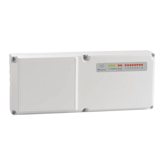
RXA01M
8-ZONE INDUSTRIAL CONTROL UNIT
•
Power supply 230V~ or 12Vdc
•
Possibility of connecting a Backup system
•
Possibility of connecting up to 8 4..20mA gas transmitters
•
Nor (Normal) or Rev (Reverse) relay logic set-up
•
Pre-alarm and Alarm thresholds set-up on two ranges
•
Enabling/Disabling of each individual input
•
Visual and acoustic signals in case of abnormal events
•
Conforms with EMC 2014/30/EU, LVD 2014/35/EU and
RoHS2 2011/65/EU
1
1
A
e r t
e s
1
1
Fig. 1: External aspect.
23 mm
2
Fig. 2: Internal view and parts.
Cable entry through
bottom openings.
Fig. 3: Cable entry instructions.
Via del Commercio, 9/11. 36065 Mussolente (VI) - ITALY
Tel.: +39.0424.567842 - Fax.: +39.0424.567849
http://www.seitron.it - e-mail: info@seitron.it
1
1
2 3
4
5 6
7
8
1
B
283 mm
F1
F2
5
C
6
6
314 mm
7
8
Cable entry through upper
slots.
1
2
Advertisement

Related Manuals for Seitron RXA01M


Summary of Contents for Seitron RXA01M
- Page 1 Possibility of connecting a Backup system Tel.: +39.0424.567842 - Fax.: +39.0424.567849 • Possibility of connecting up to 8 4..20mA gas transmitters http://www.seitron.it - e-mail: info@seitron.it • Nor (Normal) or Rev (Reverse) relay logic set-up • Pre-alarm and Alarm thresholds set-up on two ranges •...
- Page 2 powered by the same source at 12Vdc, this must be able to TECHNICAL FEATURES provide adequate current, therefore have adequate power, Power supply: 230V~ -15% +10% 50/60 Hz WARNING equal or greater than the total power absorbed by the • This control unit IS NOT suitable for installation in ATEX classified zones.
- Page 3 GENERAL INFORMATION Pre-alarm relay (FLT). JUMPER AND DIP-SWITCH SET-UP This status is signalled by switching on the yellow LED ' This device is a gas control unit equipped with 3 Outputs by switching on the red LED corresponding to the input to with exchange contacts (pre-alarm, alarm and fault relay) which the transmitter that detected the abnormal event is able to configure and control up to 8 gas concentration...
- Page 4 DIP-SWITCH LATCH - alarm status memory set-up The table on page 5 shows the Pre-alarm and Alarm TABLE 1: Pre-alarm and Alarm thresholds set-up. thresholds values that can be set (X1 o X2). 1 2 3 4 5 6 7 8 Note: ▲...
Need help?
Do you have a question about the RXA01M and is the answer not in the manual?
Questions and answers