Advertisement
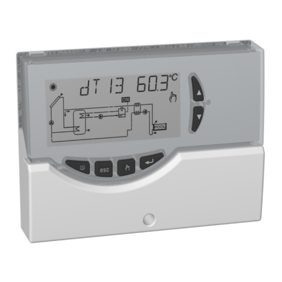
DIGITAL CONTROL UNIT
FOR THERMAL SOLAR SYSTEMS
WARNING
The installation technician shall operate in full compliance with all the applicable technical standards in order to
grant the unit safety.
DESCRIPTION OF THE KEYS
RESET KEY
MENU KEY
CANCEL KEY
KEY 'ABC FUNCTION'
1
c
SELECTION KEYS
CONFIRMATION KEY
TDST24M000SE 032635 190619
Advertisement
Table of Contents

Related Manuals for Seitron TDST24M


Summary of Contents for Seitron TDST24M
- Page 1 DIGITAL CONTROL UNIT FOR THERMAL SOLAR SYSTEMS WARNING The installation technician shall operate in full compliance with all the applicable technical standards in order to grant the unit safety. DESCRIPTION OF THE KEYS SELECTION KEYS RESET KEY CONFIRMATION KEY MENU KEY CANCEL KEY KEY ‘ABC FUNCTION’...
-
Page 2: Technical Features
OVERVIEW 0..10V: Amplitude: 0V..10V ±10%@10V Minimum load: 10KOhm. This device is a centralized control unit for thermal solar Max allowed PWM / 0...10V panels. Equipped with 3 relay outputs (2 for loads + 1 for cable length: < 3m. alarm), PWM output, 0..10V output and 3 inputs (sensors), can configure and manage up to 6 different types of solar Protection grade: IP 40... -
Page 3: Installation
INSTALLATION Fix the power unit base to the wall. WARNING! The installation technician shall operate in full compliance with all the applicable technical standards in order to grant the unit safety TO INSTALL THE DEVICE, PERFORM THE FOLLOWING OPERATIONS: Remove the central screw and the plastic door. Fit the cover again with the electronics at the base. - Page 4 : reinforced insulation WARNING! Before wiring the appliance be sure to turn the mains power off. WARNING! S1, S2 and S3 are NTC temperature sensors. For S1 sensor the -50°C..+200°C range probe (blue cable) must be used, while the probes with the range of -50°C..+110°C (yellow cable) can be used for the other probes. The outputs OUT1, OUT2 and Alarm, are voltage free.
- Page 5 EXAMPLE OF CONNECTION FOR 3-SPEED SOLAR CIRCULATORS WITH WET or “HIGH EFFICIENCY” ROTOR COMPLIANT WITH DIRECTIVE ErP 2015, WHICH DOES NOT REQUIRE AN EXTERNAL PWM SIGNAL (WITHOUT A CONNECTOR FOR PWM). Fit the door again to close the power unit. WARNING! When closing the unit please ensure that the removable wiring terminals have been inserted with the correct...
-
Page 6: Acoustic Signals
STARTING - AUTOMATIC (Normal controller operation) In this mode the control unit automatically manages and TURNING ON AND OFF controls the operation of the installation according to the To turn the control unit on and off, press the ‘ esc ’ key for programmed data (normal controller operation). -
Page 7: Installer Parameters
INSTALLER PARAMETERS Using installer parameters Inserting the correct Password gives access to the installer To access the installer parameters press the ‘ ‘ key. parameters change mode (‘ SET ’ icon lights). The first Entering the Password information displayed is the model of the control unit in use The display will show ‘PWD 0000’... -
Page 8: Control Logic
CONTROL LOGIC PRESS THE ‘ esc ’ KEY TO RETURN TO THE INSTALLER PARAMETERS SELECTION. WARNING: The following control logics must be applied to all the diagram described hereinafter. WAIT 20 SECONDS OR PRESS THE ‘ esc ’ KEY TO EXIT CONTROL LOGIC IN ABC THE INSTALLER MODE. - Page 9 AVAILABLE DIAGRAMS Solar heating installation with 1 tank and no Solar heating installation with 1 tank, direct integrative heat source. integration by means of valve logic. Control logic Control logic T1-2 T1-2 1/ 0 / 1 0 Solar heating installation with 1 tank and additional Natural circulation solar heating installation with 1 tank thermostatic heating.
- Page 10 SETTING THE THERMAL DATA Probe safety temperatures Using this parameter it is possible to set the thermal data Data Regulation range Default related to the selected installation: Note: The control unit is supplied with pre-programmed 60.0 .. 240.0 °C 140.0 °C thermal data for optimal operation.
- Page 11 Hysteresis of the safety temperatures ABC Temperature (Automatic Boiler Control) on probe Data Regulation range Default Data Regulation range Default HYTS 1.0 .. 15.0 °C 2.0 °C TABC 20.0 .. 80.0 °C 30.0 °C Thermostatic hysteresis Data Regulation range Default 1.0 ..
- Page 12 ANTIFROST PARAMETER MANAGEMENT Antifrost temperature Using this parameter it is possible to set the data managing Data Regulation range Default the antifrost function. -10.0°C .. +10.0 °C 4.0 °C The control unit is supplied with preset antifrost data for optimal operation. Any change to these values must be performed by Collector pump ‘on’...
- Page 13 ACOUSTIC SIGNAL MANAGEMENT RELAY LOGIC SELECTION Using this parameter it is possible to enable or disable the Using this parameter it is possible to reverse the output logic acoustic signalling of the control unit (keyboard tones, from Normally Open (N.O.) to Normally Closed (N.C.) and alarms, and diagnostics).
- Page 14 INTEGRATION HOURS COUNTER LIMITATION OF COLLECTOR MINIMUM TEMPERATURE Using this parameter it is possible to display the actual number of hours of the integrative source operation or reset The parameter ‘Minimum Temperature Limitation’ on collector is used to manage the Minimum Temperature Thermostat used for activation of the collector pumps.
- Page 15 PWM and 0..10V OUTPUT SETTINGS Setting the connected pump functioning logic With this parameter you can change the settings which Data Regulation range Default control the pump connected to the PWM or 0..10V output PUMP REV .. NOR of the control unit. Settings details AFTER SELECTING PARAMETER P8 PRESS THE ‘...
- Page 16 at minimum speed, while with the PWM output at maximum value %MAX or VMAX, while, if it is OFF, will be equal to the set value %OFF or VOFF. value (100%) the pump runs at full speed. Of course the If the collector pump is switched on after the intervention of pump will operate to all the intermediate speeds through the the ABC function, the regulation of the pump rotation speed...
- Page 17 collector pump speed raises gradually until it reaches the Parameters for PWM (PWM1) output maximum set speed only after the ‘ TIME ’ period control %OFF %ON .. 100% 100% has elapsed. %MAX .. %OFF If the differential temperature (∆Tr) measured between the reference sensors is lower than the set differential %MAX 0% ..
- Page 18 P10: safety temperature is reached, in order to avoid thermal VACUUM TUBES shock and air pockets in the system. In some solar systems, for example when vacuum tubes are The collector pump will automatically restart only if the installed, the collector temperature measurement could be collector temperature measured with sensor TS_1 is below slow, because of its non optimal position.
- Page 19 P11: ANTI-LEGIONELLA Enable parameter Through this parameter you can enable or disable the Anti- Data Regulation range Default legionella function. OFF / P_1 / P_0 The anti-Legionella (function activated by default) consists of a boiler’s water heating cycle at 65°C every 30 days for 5 minutes (in order to carry out thermal disinfection action against the related bacteria) only in case the water in the WARNING!
- Page 20 The setting ranges for each individual dataare listed below. FUNCTIONS ACCESSIBLE TO THE USER The functions accessible to the user are limited and do Enabling the anti-legionella function not allow setting those data influencing the installation management. Data Regulation range Default The only operations allowed to the user are the following: EN L...
-
Page 21: User Parameters
Displaying the Maximum Temperatures recorded Antifrost Activation Parameter ‘ TMAX U1 ’ allows to display the maximum The ‘ AFR U2 ’ parameter (anti-frost) enables or disables the temperature recorded in the system for each probe TM-. antifrost function. The management of the antifrost data is performed through the user parameters. -
Page 22: Troubleshooting
TROUBLESHOOTING ANOMALY POSSIBLE CAUSE The control unit has revealed an anomaly on the probe. The display shows the number of the damaged probe and the type of anomaly present. COL OPEn During normal operation Probe missing, not properly wired or open (R=∞) - Probe S_2 OPEn control unit displays the symbol is detecting a temperature lower than -31°C. - Page 23 NOTE: TDST24M000SE 032635 190619...
- Page 24 SEITRON S.p.A. a socio unico Via del Commercio, 9/11 36065 - Mussolente (VI) - ITALY Tel.: +39.0424.567842 Fax.: +39.0424.567849 www.seitron.it - info@seitron.it TDST24M000SE 032635 190619...
Need help?
Do you have a question about the TDST24M and is the answer not in the manual?
Questions and answers
How connection sensors, siren,and push button
To connect sensors, siren, and push button to the Seitron TDST24M:
Sensors:
- Use terminals labeled S1, S2, and S3.
- S1 requires a -50°C to +200°C NTC probe (blue cable).
- S2 and S3 use -50°C to +110°C NTC probes (yellow cables).
Siren:
- Connect to the Alarm relay output.
- The Alarm relay is voltage-free, rated at 4(1)A max 250V~ (SPDT).
- Ensure external power supply matches the siren requirements and relay capacity.
Push Button:
- Not specifically detailed in the context, but if used to trigger functions, it may connect to digital inputs (if available) or be wired in series with a control circuit connected to OUT1 or OUT2 relays.
- OUT1 and OUT2 are SPST, voltage-free relays:
- OUT1: 2 x 2(1)A max 250V~
- OUT2: 8(1)A max 250V~
Always make electrical connections with mains power turned off and follow grounding instructions.
This answer is automatically generated