Table of Contents
Advertisement
Quick Links
Advertisement
Table of Contents

Related Manuals for Valhalla Scientific 4176


Summary of Contents for Valhalla Scientific 4176
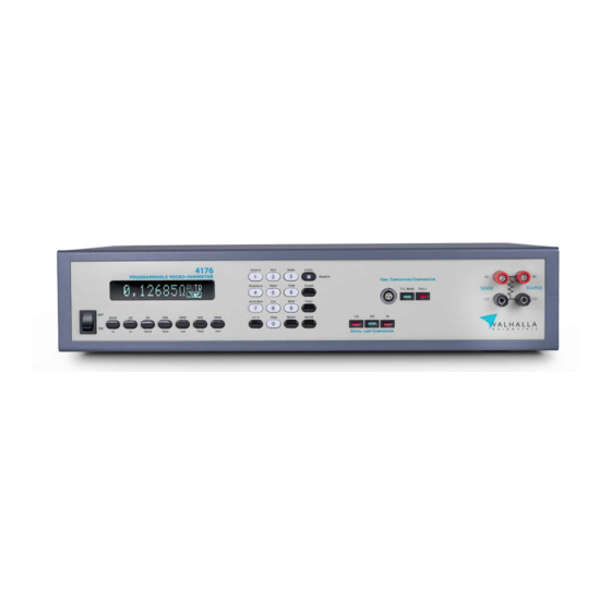
- Page 1 4176 Programmable Micro-Ohmmeter Rev. 62-1...
- Page 3 The warranty period for this instrument is stated on your invoice and packing list. Please refer to these to determine appropriate warranty dates. We will repair the instrument during the warranty period provided it is returned to Valhalla Scientific, Inc. freight prepaid. No other warranty is expressed or implied.
- Page 4 REMOVE POWER and do not use the product until safe operation can be verified by service-trained personnel. If necessary, return the product to Valhalla Scientific for service and repair to ensure that safety features are maintained.
-
Page 5: Table Of Contents
Table of Contents General Information ..........................7 Instrument Description ..........................7 Instrument Identification ......................... 7 Safety Precautions ........................... 7 Unpacking and Installing ........................8 Inspection ..............................8 Setting the Line Voltage ........................... 8 Fuse Selection ............................8 Bench Use ..............................9 Rack Mounting ............................ - Page 6 Power Connector ..........................18 HLC Relay Terminal ..........................18 Applying Power ............................19 Power-On Default Settings ........................ 19 Connecting a Load to the 4176 ......................20 Range Selection ............................. 22 Overload and Safe Mode ........................22 Measurement Modes and Functions ....................23 Standard Measurement Mode ......................
- Page 7 Using the View function ........................34 SafeMode ............................... 35 Enabling SafeMode ..........................35 Disabling SafeMode ........................... 35 Optional Features and Accessories ....................36 Options ..............................36 USB ..............................36 Accessories ............................36 Omni Compensator ..........................36 Option RX-3: Rack Mount Adapter ....................36 Test Leads ..............................
- Page 8 4176 Calibration Procedure ........................55 Standard Calibration .......................... 55 Sense Calibration ..........................55 Source Calibration ..........................56 TCM ADC Calibration ......................... 58 Special Procedures ..........................59 Addendum ............................60...
-
Page 9: General Information
Instrument Identification Valhalla Scientific instruments are identified by a two-part serial number. The Serial Tag is located on the rear or bottom of the instrument. The number is in a form of 62-0000. The first two digits, called the serial number prefix, indicate the model. -
Page 10: Unpacking And Installing
If the unit fails to operate or fails to meet the performance specifications, notify the carrier's agent and the nearest Valhalla Sales Office. Retain the shipping carton for the carrier's inspection. DO NOT return equipment to Valhalla Scientific, Inc., or any of its sales offices prior to obtaining authorization to do so. Setting the Line Voltage The line voltage selection is preconfigured according to the country to which it is shipped or as specified by the customer. -
Page 11: Bench Use
Bench Use The ohmmeter is supplied with all the hardware required for bench use and special instructions for use in this manner are not necessary. The user should become familiar with chapters 3 and 4 before attempting to operate the instrument. Rack Mounting Optional brackets are available for mounting the ohmmeter in a standard 19"... -
Page 12: Specifications
3. Specifications This section contains accuracy and operational specifications for the Model 4176. The accuracy specifications are valid for a period of one year from the date of calibration at a temperature of 15°C to 35°C. Outside this range, the temperature coefficient specification applies. -
Page 13: General Specifications
General Specifications Display: ...................... 5 Digit / Multi Section VFD 140px x 16px Overload Limit: 20mΩ Range ............................. 99.95% of Range 200mΩ thru 20kΩ Range ........................ 119.95% of Range Overload Indication: ..................... Display flashes “OVERLOAD” Terminal Configuration: ........................Four-wire Kelvin ADC Conversion Rate: ...................... -
Page 14: Getting Started
4176. Front Panel The front panel of the 4176 can be broken down into eight parts. In Figure 5 you can see the regions indicated by their name. Power Switch The power switch is a two position ON/OFF rocking switch, used to apply (ON position) or disconnect (OFF position) the AC power source from the internal circuitry of the ohmmeter. -
Page 15: Display
“AUTO”. Displays the Valhalla Scientific Logo. If a function is activated, this section Function Window of the display will alternate between the Logo and the abbreviated function name. -
Page 16: Function/Numerical Keys
The UPDATE key is used to set and/or view display update rate and intensity. PDATE The HLC key is used to enable or disable the 4176’s internal “Multi-Range Dual Limit Comparator. Also used to set and/or view the limits used. -
Page 17: Tcm Receptacle And Leds
The TCM feature of the 4176, arithmetically calculates the resistance value to display utilizing the ambient temperature and other parameters that will be present in later chapters. It is solemn for the user to be aware if the TCM mode is enabled or disabled so that the display reading may be interpreted correctly. -
Page 18: Hlc Leds
Source and Sense Binding Post Connections to the 4176 are made via the front panel source/sense terminals, which consist of two red and two black standard binding posts with gold plated brass contact material. The posts can accept standard banana plugs, wires up to 12 AWG, or spade lugs. The four terminals provide full 4-Wire Kelvin measurement capability. -
Page 19: Rear Panel
Rear Panel The rear panel of the 4176 may vary from unit to unit according to the optional features installed. This section of the manual refers to the standard model without any optional features or modifications. If the 4176 that you are using features terminals or connectors that are not described in this section, please refer to any available addendum that references the particularities of your model. -
Page 20: Fuse Holder
Fuse Holder The rear panel fuse holder provides access to the main power fuse. Fuse values are listed below: 115Vac = 0.250 Amp Slo - Blo Fuse 230Vac = 0.125Amp Slo - Blo Fuse WARNING: Replace blown fuses with their exact equivalent only! Power Connector The 3-prong power connector on the rear panel of the ohmmeter is for the application of AC power to the instrument. -
Page 21: Applying Power
Applying Power Before applying power, please refer to chapter 2. Turn on the ohmmeter by placing the front panel power switch in the ON position. If the ohmmeter does not to turn on, verify that the instrument is connected to the power line. If line power is not the problem, remove the power cord and check the line power fuse and the line voltage selection switch settings. -
Page 22: Connecting A Load To The 4176
The first step in using the ohmmeter is to connect to a load. Valhalla Scientific, Inc. offers several different test leads that can be used with the Model 4176 and other Valhalla ohmmeter models (see chapter 5 for a list of available test leads). All ohmmeter test leads are composed of a pair of leads, both terminated in a multi-stacking dual banana plug. - Page 23 For hard-to-reach surfaces, Valhalla Scientific offers two different sets of spring-loaded dual needle probes that differentiate in overall size and distance between the needles.
-
Page 24: Range Selection
Range Selection The ohmmeter is designed to automatically start up in Auto-Range. The display range window will show “AUTO”. While in Auto-Range, the instrument will automatically select the range that will display the measured resistance with the greatest resolution possible. In many applications where the test current is critical, the user should manually select a range. -
Page 25: Measurement Modes And Functions
In many applications the contact resistance can exceed the value of the load by several orders of magnitude. The 4176 bypasses this potential error source by providing two terminals of constant current and an additional two terminals for high impedance voltage measurement. -
Page 26: Tcm" - Temperature Compensated Measurement Mode
After all the variables are determined, the 4176 automatically calculates the compensated resister value. Here is an example of the equation. Let us assume that we are measuring a copper wire, and we wish to know the resistance value at a temperature of 20°C. -
Page 27: Omni Compensator
TCM key. The display will briefly read “TCM OFF”. TCS – Temperature Compensator Setup As describe earlier in this chapter, the 4176 needs to reference a temperature coefficient and a temperature reference to calculate the compensated value. Stored in the instrument’s memory are six configurations that can be selected. - Page 28 The following procedure illustrates how to select one if these configurations and how to setup a customized configuration. This procedure does not need to be repeated every time the TCM mode is selected. The configuration that is selected or the custom values inputted will be set as default. Press “F .
-
Page 29: Tcc - Temperature Compensator Calibration
TCC – Temperature Compensator Calibration This procedure is used to match a 4176 with its Omni Compensator. Verify that the instrument is in a temperature-controlled area. Press “F . + TCM + 2” to initiate the process. Connect the Omni Compensator to the TCM receptacle on the front panel of the Ohmmeter. -
Page 30: Hlc" - Hi-Lo Comparator Mode
HLC mode. If, for example, the resistors to be inspected and tested are 1 KΩ ± 0.1%, the 4176 would be set on the 2kΩ range; the upper limit would be set at 1.0010kΩ, and the lower limit to 0.9990kΩ. -
Page 31: Setting The Limits
Setting the Limits Each range has a different set of limits that can be programmed by the user. Table 5 lists the default values programmed for each range. Once the user sets new values, the default settings will be overwritten, and the user settings will be stored in memory. -
Page 32: Hlc On
HLC ON To start working with the HLC mode, simply select the correct range for your load and press the “HLC”. The screen will briefly display “HLC ON”. The instrument will also perform an LED check-sequence. Make sure that all three of the HLC LEDs illuminate. After the LED check-sequence, only one of the three HLC LEDs will remain illuminated. -
Page 33: Update Function
Update Function The Update function is designed to allow the user to set the display update rate and the display intensity. The user can choose from a list of five possible display update rates and eight levels of display intensities. Display Update Rate The display update rate indicates the time interval in-between every display update. -
Page 34: Run/Hold Function
Run/Hold Function The Run/Hold function of the 4176 can be configured in three different ways: RUN/HOLD When configured for Run/Hold, pressing the “R /Hold” key will freeze the readings on the display. The function window displays “HOLD”. To exit the hold state, press “R ”... -
Page 35: Print/Log Function
Print/Log Function The Print/Log function allows the user to receive the measurements through the instrument’s RS-232 or USB interface. A serial terminal of a PC can be used to capture the readings. The measurements can also be logged to an Excel spreadsheet by using a Data Sources Open Database Connectivity (ODBC) to access data from the ohmmeter. -
Page 36: View Function
View Function The View function allows the user to view how the instrument’s functions are configured. This function is easy to use and is very useful especially for HLC and TCM users. Using the View function Press “V ” followed by one of the following keys: UPDATE - The screen shows the display update rate and intensity settings. -
Page 37: Safemode
SafeMode As a safety precaution, the 4176 is designed with an optional Safe Mode feature. With the Safe Mode option activated, if an overload persists for more than 10 seconds, the 4176 shuts down its current source, and displays “SAFEMODE” on its screen. The ohmmeter does not automatically recover from safe mode;... -
Page 38: Optional Features And Accessories
Option RX-3: Rack Mount Adapter The 4176 Micro-Ohmmeter may be mounted in a standard 19" equipment rack using a set of optional rack ears. Option RX-3 comes with all the necessary hardware for installation and mounting. Test Leads This section details the different test lead sets and connectors available for use with the 4176 Micro- Ohmmeter. -
Page 39: Needle Type Probes
KK: Heavy-Duty Lead Set "KK" is a 4-wire Kelvin cable set, 48-inches in length terminated in heavy-duty gold-plated clamps. Figure 3. JAWS: Gold-Plated Clamps "JAWS" are gold-plated heavy-duty clamps. Clamps open to 2 inches for connection to large motors, bushings, etc. Figure 3 - KK: Kelvin 4-Wire Lead Set Needle Type Probes MP-1: Kelvin Micro-Probes... -
Page 40: Remote Operations
The RS232 interface provides a point-to-point connection between two items of equipment such as a computer and the 4176. There are some parameters you need to set on both sides. Once you have set these parameters, you can control the 4176 through the RS232 interface. -
Page 41: Connecting To A Computer
Should return the Manufacturer, model number, serial number, and firmware version in the following format: VALHALLA SCIENTIFIC 4176,1.81,0" If you do not receive a proper response from the 4176, please check if the power is on, and all cable connections are active. INPUT AND OUTPUT QUEUE... -
Page 42: Combining Commands
RANGE 4; HLCHI 14.999<LF> Synopsis of Commands The tables in this section summarize the commands of the programmable 4176 Ohmmeter. DETAILS OF COMMAND REFERENCE Each command in this section will give a detailed description. The examples of each command will be provided and what query form might return. - Page 43 CALDATE QUERY Request the last calibration date and technician initials. Syntax: CALDATE? Response: "00-00-04 VSI" Power-on default = "00-00-00 VS####" *CLS COMMAND Sets buffers to power on default. Syntax: *CLS<crlf> CNFG COMMAND Turns on and off system configuration items. Alarms, key beeps, other features. Syntax: CNFG <item number>, <ON or OFF>...
- Page 44 FAULT COMMAND Sets an alarm fault to watch the system react. Syntax: FAULT <Hexadecimal number> FAULT_ALARM_NO_FAULT FAULT_ALARM_OVER_TEMP Internal temperature too high FAULT_ALARM_CAL_LIMIT Input level for calibration exceeded limit FAULT_ALARM_TCM Input level for TCM calibration exceeded limits FAULT_ALARM_CMD_CHAR Unprintable characters received / cmd too long FAULT_TXBUF_SPACE Low on space in transmit buffer FAULT_ALARM_TXBUF_FULL...
- Page 45 HLC COMMAND Selects HLC mode on or off Syntax: HLC <ON or OFF> Example: HLC ON<crlf> HLC?<crlf> ON<crlf> Power-on default = OFF Note: HLC mode on puts the logic level HLC relays on the rear panel connector and the ranges on the relays outputs. See HLC relay contact descriptions. HLC QUERY Responds with HLC mode on or off Syntax:...
- Page 46 HLCHI? QUERY Reads the Hi-Lo Comparator high value from RAM for range. Syntax: HLCHI? Response: Floating (fixed) point Ohm value for current range. "1.0000" for 1Ω in the 2Ω range and 100.00 for 100mΩ in the 200mΩ range. This command reads the value from RAM memory only. If you have used the HLCHI command to write a HLC value it will be different than the value stored in non-volatile memory if the SAVSETUP command has not been sent.
- Page 47 *IDN? QUERY Returns the RS-232 identification string from non-volatile. Syntax: *IDN?<crlf> Response: ID string "VALHALLA SCIENTIFIC 4176,1.01G,0" Example: *IDN?<crlf> "VALHALLA SCIENTIFIC 4176,1.01G,0"<crlf> ID_STRING "VALHALLA SCIENTIFIC" VERSION "1.01G" MODEL "4176" HARDWARE_VER "0" OPTION_STRING "Option(s) : "...
- Page 48 KEY COMMAND Presses a key from the interface, use for macros when the command you desire is not listed here. Syntax: KEY <key number> Response: <crlf> (only after the key has been processed) Key number = 0 - 24 KEY_NO_KEY KEY_RANGE_1 KEY_0 KEY_4...
- Page 49 KEY? QUERY Returns the decimal number of the key last key processed by the state machine. This query returns any key in the remote mode even if the key is locked out by remote mode, i.e. KEY_LOCAL is not locked out. Syntax: KEY?<crlf>...
- Page 50 LOCAL COMMAND Returns meter to local mode, remote LED off, Goto Local. Syntax: LOCAL Returns: <crlf> Power-on default = LOCAL mode Notes: REMOTE mode is selected when the meter receives a valid character (not <crlf>. Once selected, all keys are disabled and will not be scanned. Therefore, no key beeps with the exclusion of the LOCAL key at the top right of the key pad.
- Page 51 OHMS? QUERY Responds with reading from the front panel display and causes an immediate update of the conversion so repeated query requests gets most accurate data. Send range command or AUTO prior to sending this to get the scaling factor. The Ohms omega, milli and kilo characters are removed during remote formatting.
- Page 52 RANGE? QUERY Returns the selected range. Syntax: RANGE? Response: Range number = 0 – 7 0 = RANGE_OFF (SAFE MODE) 1 = R20mOHM 2 = R200mOHM 3 = R2_OHM 4 = R20_OHM 5 = R200_OHM 6 = R2K_OHM 7 = R20K_OHM A = RANGE_AUTO RDNG? QUERY Responds with reading from the device in engineering notation.
- Page 53 RESET COMMAND Executes a soft reset of the ADuC834 processor system. Syntax: RESET Response: Front panel display show soft reset initiation. "RESETTING" is displayed flashing inverse mode for 300ms while all system configurations are returned to power up default. Example: RESET<crlf>...
- Page 54 *STB? QUERY Returns the command status byte. Syntax: *STB? Response: Command status number = 0 - 0xFF Example: *STB?<crlf> 01<crlf> Fragment: TCM ON<crlf> *STB?<crlf> TCM AFF<crlf> **STB?<crlf> (returns * ERROR) 03<crlf> TCM?<crlf> ON<crlf> 0 = CMD_LAST_COMPLETE 1 = CMD_UNKNOWN 2 = CMD_MISSING_PARAM 4 = CMD_INVALID_PARAM 8 = CMD_MODE_OFF 16 = CMD_INCORRECT_NUMBER_PARAMS...
- Page 55 TCM COMMAND Selects TCM mode on or off Syntax: TCM <ON or OFF> Example: TCM ON<crlf> TCM?<crlf> ON<crlf> Power-on default = OFF TCM QUERY Responds with TCM mode on or off Syntax: TCM? Example: TCM?<crlf> ON<crlf> Response: <"ON" or "OFF"> Power-on default = OFF Send this date after the calibration is complete followed by a SAVESETUP to store in EE memory.
-
Page 56: Routine Maintenance
General This Chapter provides general maintenance information and a procedure for calibrating the ohmmeter. The Model 4176 µ-ohmmeter should be calibrated on a routine basis (every 12 months is recommended) to ensure continued accuracy. Before performing the calibration procedure below, the ohmmeter should be allowed to warm up at a stable temperature for at least 30 minutes with the covers in place. -
Page 57: 4176 Calibration Procedure
The sense calibration and the final adjustment calibration is cover-on and automated; the instrument will prompt the user throughout the steps. The source calibration is performed by adjusting potentiometers located on the 4176 main board. All three calibrations must be performed for a complete calibration of the 4176. -
Page 58: Source Calibration
4. Remove the DVM connection and the jumper. 5. Select the .2Ω range. 6. Connect the 4176 to a .1Ω standard resistor. 7. Adjust RV2 for a display reading equal to the value of the load. 8. Select the 2Ω range. - Page 59 21. Connect the 4176 to a 10kΩ standard resistor. 22. Adjust RV7 for a display reading equal to the value of the load. 23. Reset the 4176 from the front panel RESET button or by turning off the power switch and rebooting.
-
Page 60: Tcm Adc Calibration
TCM ADC Calibration Remove the top cover of instrument. Verify that the Omni Compensator (Temp. Sensor) is not connected to the ohmmeter. Press “E ” to continue. NTER The instrument will perform the TCM Zero Cal. The screen will display the following information: II. -
Page 61: Special Procedures
Special Procedures Noisy Readings In general, noisy readings are caused by poor connections either to the input terminals or to the test load. If noisy readings are encountered, check these connections first. Inductive Loads The measurement of highly inductive loads (such as large transformers) may also yield noisy readings. This is due to the very high impedance to line voltage exhibited by the load causing an excessive amount of noise pick-up. -
Page 62: Addendum
If no items follow this page, your manual is complete as printed. For repair and calibration services, call 800-548-9806 or visit valhallascientific.com. Email support available at support@valhallascientific.com 4176 Programmable Digital Micro-Ohmmeter User Manual Revision 62-1 (2021) Copyright © 2021 Valhalla Scientific, Inc. All rights reserved. - Page 64 4176 Programmable Digital Micro-Ohmmeter User Manual Revision 62-1 (2021) Copyright © 2021 Valhalla Scientific, Inc. All rights reserved...
Need help?
Do you have a question about the 4176 and is the answer not in the manual?
Questions and answers