
Related Manuals for Vertiv NetSure M830B


Summary of Contents for Vertiv NetSure M830B
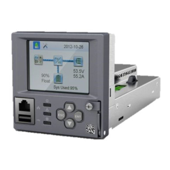
- Page 1 NetSure™ Control Unit (NCU) Controller User Manual Specification Number: 1M830BNA, 1M830DNA Model Number: M830B, M830D Software Version 1.2.30...
- Page 2 The information contained in this document is subject to change without notice and may not be suitable for all applications. While every precaution has been taken to ensure the accuracy and completeness of this document, Vertiv assumes no responsibility and disclaims all liability for damages resulting from use of this information or for any errors or omissions.
-
Page 3: Table Of Contents
Vertiv™ NetSure™ Control Unit (NCU) User Manual TABLE OF CONTENTS Admonishments Used in this Document ........................viii Important Safety Instructions ............................ix Static Warning ..................................x 1 Introduction ..................................1 1.1 Preface ........................................................1 1.2 Overview ......................................................... 1 1.3 Function Descriptions ................................................2 1.3.1... - Page 4 Vertiv™ NetSure™ Control Unit (NCU) User Manual 2.7.7 Connecting a Local Computer Directly to the Controller when the System IS Equipped with an IB4 Board ....................................................24 2.7.8 Disabling Proxy Server Settings to Enable a Connection to the Controller over an Intranet Network (if required) ................................................
- Page 5 Vertiv™ NetSure™ Control Unit (NCU) User Manual 2.9.38 Setting Temperature Sensors ........................................ 39 2.9.39 Setting Battery Charge Temperature Compensation ............................40 2.9.40 Setting Battery Thermal Runaway Management (BTRM) Feature ..................... 40 2.9.41 Configuring the NCU Identification of Rectifiers and Assigning which Input Feed is Connected to the Rectifiers ..................................................
- Page 6 Vertiv™ NetSure™ Control Unit (NCU) User Manual 3.4 Controller Information Menu (accessed from the Main Menu) ............................. 88 3.5 Alarm Menu ....................................................89 3.6 Settings Menu ....................................................90 3.7 Start Wizard Sub-Menu (accessed from Settings Menu) ..............................96 3.8 Input Power Menu ..................................................97 3.9 Module Menu ....................................................
- Page 7 Vertiv™ NetSure™ Control Unit (NCU) User Manual 6.3 MIB Installation ..................................................230 6.3.1 Installation ................................................230 6.3.2 Contents of the Controller’s MIB ....................................... 230 6.4 Accessing the Controller through an NMS ....................................230 6.4.1 Apply Administrative Privilege ......................................230 6.5 ESR Configure ................................................... 230 7 Accessing the NCU via TL1 ............................
-
Page 8: Admonishments Used In This Document
Vertiv™ NetSure™ Control Unit (NCU) User Manual Admonishments Used in this Document will likely DANGER! Warns of a hazard the reader be exposed to that will result in death or serious injury if not avoided. (ANSI, OSHA) could WARNING! Warns of a potential hazard the reader... -
Page 9: Important Safety Instructions
Vertiv™ NetSure™ Control Unit (NCU) User Manual Important Safety Instructions Safety Admonishments Definitions Definitions of the safety admonishments used in this document are listed under “Admonishments Used in this Document” on page viii. General Safety DANGER! YOU MUST FOLLOW APPROVED SAFETY PROCEDURES. -
Page 10: Static Warning
Vertiv™ NetSure™ Control Unit (NCU) User Manual Static Warning This equipment contains static sensitive components. The warnings listed below must be observed to prevent damage to these components. Disregarding any of these warnings may result in personal injury or damage to the equipment. -
Page 11: Introduction
1 Introduction 1.1 Preface These instructions describe the complete functionality of the Vertiv™ NetSure™ Control Unit (NCU). Some functionality is dependent on hardware connected to the NCU. Your system may not utilize all the functionality described. Refer also to the NCU Configuration Drawing (C-drawing) furnished with your system for a list of factory default settings. -
Page 12: Function Descriptions
Vertiv™ NetSure™ Control Unit (NCU) User Manual Figure 1.1 Interfacing with the NCU 1.3 Function Descriptions 1.3.1 Rectifier, Solar Converter, and Converter Control The NCU controls rectifiers, solar converters, and converters automatically. NOTE! Solar Mode has to be enabled for NCU control of solar converters (see “Enabling Solar Mode” on page 38). -
Page 13: Operating Data Acquisition And Data Logs
Vertiv™ NetSure™ Control Unit (NCU) User Manual The available system alarms can also be mapped to alarm relays (located on controller interface boards) that can be wired to external alarm circuits. Table 1.1 Alarm Severity Levels Alarm Yellow Audible Severity Levels... -
Page 14: Battery Management
Vertiv™ NetSure™ Control Unit (NCU) User Manual 1.3.4 Battery Management The NCU provides the following battery management functions. • Battery Charge Temperature Compensation • Battery Equalize Charge • Battery Charge Current Limit • High and Low Battery Temperature Alarms •... - Page 15 Vertiv™ NetSure™ Control Unit (NCU) User Manual Figure 1.2 Temperature Compensated Voltage Control TempComp Coeff setting (mV/°C). Upper voltage level where temperature compensation clamps the voltage. Limited to the TEMP COMP MAX V high 1V Max (24V System) setting. 2V Max (48V System) Nominal voltage (voltage at nominal temperature).
- Page 16 Vertiv™ NetSure™ Control Unit (NCU) User Manual High and Low Battery Temperature Alarms The NCU can monitor battery temperature via a temperature sensor mounted on a battery cell. Values for high battery temperature and low battery temperature alarms can then be programmed into the NCU.
- Page 17 Vertiv™ NetSure™ Control Unit (NCU) User Manual The battery voltage drops below the preset End Test Voltage (Vend) (see Figure 1.4). The battery has not passed the test and the test is interrupted. A bad battery alarm is activated. If a critical alarm occurs during the test or there’s not enough load, the battery test is aborted. In such cases a “Battery Test Fail”...
-
Page 18: Energy Management
Vertiv™ NetSure™ Control Unit (NCU) User Manual 1.3.5 Energy Management Energy Management consists of an Energy Optimization Mode. Energy Optimization Mode The NCU provides an Energy Optimization Mode (ECO) function. Energy Optimization permits an installation to only operate rectifiers as needed to maintain the load and keep batteries in a fully charged condition. As load increases, Energy Optimization turns on additional rectifiers as needed to maintain the load. -
Page 19: Power Split Feature
Vertiv™ NetSure™ Control Unit (NCU) User Manual If the system enters the ECO mode and then exits for five consecutive times within one hour, an abnormal alarm (ECO Cycle Alarm) will be generated and the system can no longer enter the ECO mode until the ECO Cycle Alarm is cleared manually or retires automatically after 24 hours. -
Page 20: Diesel Management Feature
NOTE! The Hybrid Control function requires a specific configuration. Hybrid Control menus will not normally be displayed unless your NCU has been configured by Vertiv for this function. Contact Vertiv for a Hybrid Control configuration. General Hybrid Control allows the option of selecting one of the following: Fixed Daily Time based operation or Capacity Discharge based operation. - Page 21 Vertiv™ NetSure™ Control Unit (NCU) User Manual Hybrid Operation Generator Control: A potential free relay contact output from the NCU interface board controls the start and stop of the diesel generator. The signal will be generated by the NCU and operates according to the Hybrid software mode of operation. The default control logic (User selectable) is as follows: •...
- Page 22 Vertiv™ NetSure™ Control Unit (NCU) User Manual Float Charge: Default float voltage is 54.0 V at 20°C with a temperature compensation of 72 mV per °C. If battery temperature exceeds the BTRM Temp High 2 alarm set point, the charge voltage is reduced to 48 V to reduce gassing and prevent thermal runaway.
- Page 23 Vertiv™ NetSure™ Control Unit (NCU) User Manual recharge process will follow the recharge profile shown in Figure 1.6. If battery becomes fully recharged and grid power is still present, the operations will continue to be powered from grid and no battery discharge will be initiated for the duration of grid availability. In this case, battery voltage will revert back to Float voltage.
-
Page 24: Supervisory Module (Sm Modules) Monitoring
Vertiv™ NetSure™ Control Unit (NCU) User Manual High Load Alarm: In order to identify conditions where the load requirements are exceeding the dimensioning of the Hybrid site, an alarm will be generated. The alarm will be triggered when the maximum capacity per discharge cycle is exceeded. The threshold value will be set as default to 40% of battery capacity. -
Page 25: Fiamm Sonick (Sodium Nickel) Battery Interface
Vertiv™ NetSure™ Control Unit (NCU) User Manual The relay outputs can be connected to customer external alarm circuits. Each relay output can be configured to change state when one or more alarm events occur. The relay outputs can also be connected to customer external equipment, so that the relay output can control or interface with the customer external equipment. - Page 26 Vertiv™ NetSure™ Control Unit (NCU) User Manual The NCU sends the Service-Type attribute. The Service-Type attributes supported are: Login – browser privilege level. Outbound – operator privilege level. Administrative – admin privilege level. NAS Prompt – engineer privilege level. If the server responds with an unknown Service-Type, the NCU will record the event it in the system log and act as though access was rejected, per RFC 2865.
-
Page 27: Operation
Vertiv™ NetSure™ Control Unit (NCU) User Manual 2 Operation 2.1 Controller Initialization The controller goes through an initialization process when power is initially applied to the system. NOTE! The initialization routine takes several minutes. During that time various alarm indicators may illuminate on the controller’s front panel and an audible alarm may sound. -
Page 28: Local Indicators
Vertiv™ NetSure™ Control Unit (NCU) User Manual System information is displayed in multiple screens. Press the ESC key to view other system information. Press the down arrow key to view the next screen. Press the ESC key to return to the Main Menu. -
Page 29: Using The Local Keypad And Display
Vertiv™ NetSure™ Control Unit (NCU) User Manual 2.3 Using the Local Keypad and Display See also “Passwords and Privilege Levels” on page 20. 2.3.1 Local Menu Navigation Keys and Local Display There are four (4) menu navigation keys and a local display located on the NCU’s front panel. Refer to Table 2.2 for the function of the menu navigation keys. -
Page 30: Using The Web Interface
Vertiv™ NetSure™ Control Unit (NCU) User Manual 2.4 Using the Web Interface See also “Passwords and Privilege Levels” on page 20. NOTE! The NCU supports a 10/100M Ethernet connection. 2.4.1 Overview Via the Web Interface, a User (with proper access level) can: •... -
Page 31: Setting Ipv6 Communications Parameters (If Controller Not Set As Dhcpv6)
Vertiv™ NetSure™ Control Unit (NCU) User Manual • IP Address: 192.168.1.2 • Subnet Mask Address: 255.255.255.0 • Gateway Address: 192.168.1.1 Local Menu Navigation: Main Menu / Settings Icon / Comm Settings / enter parameters. Web Menu Navigation: Advance Settings Menu / Ethernet Tab / enter parameters. -
Page 32: Ib4 Board
Vertiv™ NetSure™ Control Unit (NCU) User Manual “Setting for DHCP and DHCPv6” on page 21 to set the port as DHCP or DHCPv6. 2.7.5 Connecting the Controller to your Local Area Network (LAN) when the System IS Equipped with an IB4 Board NOTE! Your system may be furnished with an IB4 board. - Page 33 Vertiv™ NetSure™ Control Unit (NCU) User Manual Subnet Mask: Default Gateway: Example: IP Address: 192.168.1.2 Subnet Mask: 255.255.255.0 Default Gateway: 192.168.1.1 IPv6 IPv6 Address: IPv6 Prefix: IPv6 Gateway: Example: IPv6 Address: 20fa:fffd:fffc:fffb:fffa:fff9:fff8:fff7 IPv6 Prefix: IPv6 Gateway: 20fa:1:fffe:ffff:fffe:fffd:ffff:fffe Change your local computer’s network settings using the information you acquired in the above step, except that the last part of the IP address needs to be replaced with any different number.
-
Page 34: Connecting A Local Computer Directly To The Controller When The System Is Equipped With An Ib4
Vertiv™ NetSure™ Control Unit (NCU) User Manual 2.7.7 Connecting a Local Computer Directly to the Controller when the System IS Equipped with an IB4 Board NOTE! Your system may be furnished with an IB4 board. The IB4 board provides a second Ethernet port. The Ethernet port located on the NCU Controller’s front panel can ONLY be used to connect a computer directly to the NCU. -
Page 35: Internet Security Settings For Loading Files Or Downloading Files Into The Ncu
Vertiv™ NetSure™ Control Unit (NCU) User Manual Select Internet Options from the Tools menu. The “Internet Options” window opens. In the “Internet Options” window, select the Connections tab. Click on the LAN Settings... button. The following window opens. In the LAN Settings window, uncheck the Proxy Server box and click OK. - Page 36 Vertiv™ NetSure™ Control Unit (NCU) User Manual Select Internet Options from the Tools menu. The “Internet Options” window opens. In the “Internet Options” window, select the General tab. Under “Browsing History”, click on the Settings button. The following window opens. In the Settings window, choose “Every...
- Page 37 Vertiv™ NetSure™ Control Unit (NCU) User Manual In the “Internet Options” window, select the Security tab. Click on Trusted sites. With “Trusted sites” selected, click “Sites”. The following window opens. Uncheck the “Require server verification (https:) for all sites in the zone:” box if https is not being used.
- Page 38 Vertiv™ NetSure™ Control Unit (NCU) User Manual In the Trusted sites window, type or copy the NCU URL in the “Add this website to the zone:” box. Click Add. The NCU URL is listed in the Websites: box. Click Close.
-
Page 39: Logging Into The Controller Via Web Interface Access
Vertiv™ NetSure™ Control Unit (NCU) User Manual 2.8 Logging into the Controller via Web Interface Access Procedure Internet Explorer, version 6 or newer, is supported (IE 8.0 is recommended). Chrome, Safari, and Firefox are also supported. In your browser, enter http:// and the controller’s IP address (see “Connecting a Local Computer Directly to the Controller when the System is NOT Equipped with an IB4 Board”... - Page 40 Vertiv™ NetSure™ Control Unit (NCU) User Manual After entering a valid User Name and Password and clicking LOGIN, the Web Interface "HOMEPAGE" window opens. Refer to “Web Interface Screens” on page 110.
-
Page 41: Common Tasks Performed Via The Local Keypad And/Or Web Interface
Vertiv™ NetSure™ Control Unit (NCU) User Manual 2.9 Common Tasks Performed via the Local Keypad and/or Web Interface 2.9.1 General Refer also to “Local Display Menus” on page 85 and “Web Interface Screens” on page 110 for menu item descriptions. -
Page 42: Clearing Or Resetting Alarms
Vertiv™ NetSure™ Control Unit (NCU) User Manual 2.9.7 Clearing or Resetting Alarms Local Menu Navigation: Main Menu / Settings Icon / Alarm Settings / select alarm to clear or reset. Web Menu Navigation: Settings Menu / navigate the various device tabs to select an alarm to clear. -
Page 43: Adding, Deleting, And Modifying Users
Vertiv™ NetSure™ Control Unit (NCU) User Manual Web Menu Navigation: Settings Menu / Time Settings Tab. In the Specify Time section, click on "Get Local Time from Connected PC" and then “Set” to automatically set the date and time. To manually set the date and time, click on “the clock symbol”... -
Page 44: Setting Snmp Parameters
Vertiv™ NetSure™ Control Unit (NCU) User Manual Local Menu Navigation: Main Menu / Settings Icon / Comm Settings / DHCP (set to enabled) (can also view acquired IP address). Main Menu / ESC (to view acquired IP address). Web Menu Navigation: None. -
Page 45: Programming The Audible Alarm Feature
Vertiv™ NetSure™ Control Unit (NCU) User Manual • Equalize Start Capacity • Equalize Stop Current • Equalize Stop Delay Time • Maximum Equalize Charge Time 2.9.19 Programming the Audible Alarm Feature Local Menu Navigation: Main Menu / Settings Icon / Alarm Settings / Audible Alarm. -
Page 46: Assigning Severity Level To Alarms
Vertiv™ NetSure™ Control Unit (NCU) User Manual 2.9.22 Assigning Severity Level to Alarms Local Menu Navigation: None. Web Menu Navigation: Advance Settings Menu / Alarms Tab and DI Alarms Tab. 2.9.23 Assigning Relays to Alarms Local Menu Navigation: None. Web Menu Navigation: Advance Settings Menu / Alarms Tab and DI Alarms Tab. -
Page 47: Setting Rectifier High Voltage Shutdown
Vertiv™ NetSure™ Control Unit (NCU) User Manual Local Menu Navigation: Main Menu / Settings Icon / Batt Settings / Batt1 Settings or Batt2 Settings / Rated Capacity. Web Menu Navigation: Settings Menu / Battery Tab / Batt1 Rated Capacity and Batt2 Rated Capacity. -
Page 48: Enabling Solar Mode
Vertiv™ NetSure™ Control Unit (NCU) User Manual are used on the rectifier output, the batteries should support the load until the current limit set points can be re-established due to loss of a rectifier. 2.9.33 Enabling Solar Mode When solar converters are all installed prior to applying power and starting system, the NCU will NOT communicate with solar converters until SOLAR MODE is enabled. -
Page 49: Setting Temperature Sensors
Vertiv™ NetSure™ Control Unit (NCU) User Manual 2.9.38 Setting Temperature Sensors Temperature sensors may be connected to the… • System Temperature Ports 1, 2, 3 (if available), • Temp1 and Temp2 ports on an IB2 Interface Board, • Temp1 and Temp2 ports on an EIB Interface Board, •... -
Page 50: Setting Battery Charge Temperature Compensation
Vertiv™ NetSure™ Control Unit (NCU) User Manual Web Menu Navigation: Settings Menu / Battery Tab / Temp Compensation Probe. Also enter values for the compensation temperature alarms from the Web Interface (Settings Menu / Battery Tab). If desired, set a temperature sensor set as a battery temperature sensor as the BTRM sensor. -
Page 51: Configuring The Ncu Identification Of Rectifiers
Vertiv™ NetSure™ Control Unit (NCU) User Manual Set an ambient temperature sensor as the sensor which displays the ambient temperature on the Web Interface’s Homepage (see “Setting Temperature Sensors” on page 39). Enter values for the following parameters: “BTRM Temp Sensor”, “BTRM Temp High 2”, “BTRM Temp High1”, “BTRM Temp Delta Over Ambient”, “BTRM Temp Delta Alarm”, “BTRM Action”... -
Page 52: Setting Digital Inputs
Vertiv™ NetSure™ Control Unit (NCU) User Manual 2.9.44 Setting Digital Inputs Local Menu Navigation: None. Web Menu Navigation: Advance Settings Menu / DI Alarms Tab 2.9.45 Setting Battery Block and Battery Midpoint Monitoring (if equipped with an EIB Assembly) Local Menu Navigation: None. -
Page 53: Setting External Shunts (Connected To The Smdu+ Assembly)
Vertiv™ NetSure™ Control Unit (NCU) User Manual WEB Menu Navigation (for shunts set as battery): See “Individual Battery Settings Page” on page 133. Parameters • EIB#Battery #, Rated Capacity 2.9.47 Setting External Shunts (connected to the SMDU+ Assembly) Local Menu Navigation: None. -
Page 54: Setting The Sm-Due Parameters (If Furnished)
Vertiv™ NetSure™ Control Unit (NCU) User Manual • Break Value (Device Rating) • High 1 Curr Limit Alarm (% of Breaker Value) • High 1 Curr Alarm Severity • High 1 Curr Alarm Relay • High 2 Curr Limit Alarm (% of Breaker Value) •... - Page 55 Vertiv™ NetSure™ Control Unit (NCU) User Manual Web Menu Navigation: Advance Settings Menu / Custom Inputs Tab / SMDUE # / Input Block #, press “Modify” and select “Enable” for the fuse alarm input. When done, press “Set”. Close the window by clicking on the X button.
-
Page 56: Setting The System Current Alarm
Vertiv™ NetSure™ Control Unit (NCU) User Manual Go to the Settings Menu > Temp Probes Tab and set the temp probe parameters. 2.9.50 Setting the System Current Alarm Local Menu Navigation: None. Web Menu Navigation: Settings Menu / System Tab / System Current Alarm (Enter a value in AMPS). If system current exceeds this value, a system current alarm is issued. -
Page 57: Clearing The Maintenance Alarm
Vertiv™ NetSure™ Control Unit (NCU) User Manual NOTE! The relay test can be exited at any time by setting the Relay Test to Disabled. Manual Test When placed in Relay Manual Test Mode, all relays on an IB2 board, EIB board, and NCU de-energize (since Fail Safe is enabled relay 1 on the 1st IB2 will be in alarm state, if wired for fail safe). -
Page 58: Updating The Ncu Controller's Device Inventory
Vertiv™ NetSure™ Control Unit (NCU) User Manual Start the battery discharge test. Local Menu: Main Menu / Settings Icon / Maintenance / BattTestControl. Web Menu: Settings Menu / Battery Test / Battery Test Control. Wait for the test to end. -
Page 59: Upgrading The Ncu Using An Application ("All") Package
Vertiv™ NetSure™ Control Unit (NCU) User Manual 2.9.58 Upgrading the NCU Using an Application ("All") Package This procedure is typically used to upgrade your NCU when a new release of firmware is available for your application. The name of the Application "All" Package file must end in .tar or .tar.gz. An Application “All” package file has both the application (software) and configuration settings file and is usually supplied for an application upgrade. -
Page 60: Rebooting The Controller
Vertiv™ NetSure™ Control Unit (NCU) User Manual NOTE! SOME SYSTEMS REQUIRE CHANGES TO THE NCU CONFIGURATION DURING FINAL TEST BEFORE BEING SHIPPED. These systems are supplied with a USB memory device that contains a “SettingParam.tar” file as shipped. If provided, the “SettingParam.tar” file has a seven-digit UIN (Unique Identification Number) preceding the “SettingParam.tar”... -
Page 61: Power Split Feature
Vertiv™ NetSure™ Control Unit (NCU) User Manual Local Menu Navigation: none. Web Menu Navigation: Settings Menu / Rectifier Tab / “Rectifier Upgrade” (change to Enabled). then Settings Menu / Rectifier Tab / “Normal Update” (change to Yes) Go to the General Status Tab. See “General Status Tab” on page 136. As the rectifiers are programmed, the “Update OK Number” in the General Status Tab increments and the “Update State”... - Page 62 Vertiv™ NetSure™ Control Unit (NCU) User Manual • Proportion Coeff: The proportional coefficient that the power system designated as “System A” in a "Power Split" configuration is set to. It is suggested to leave this value at the default (30%).
- Page 63 Vertiv™ NetSure™ Control Unit (NCU) User Manual • The float voltage, equalize voltage, and battery test voltage of the NCU power system must be set to the same levels as that of the existing power system. • The remote sense, if available and connected, of both the NCU power system and existing power system must be connected to the same point.
- Page 64 Vertiv™ NetSure™ Control Unit (NCU) User Manual DC Output and Battery Voltages DANGER! Connecting the NCU power system to an existing power system for “Power Split” mode involves working on live equipment carrying live loads. This system produces DC Power and may have a battery source connected to it. Although the DC voltage is not hazardously high, the rectifiers and/or battery can deliver large amounts of current.
- Page 65 Vertiv™ NetSure™ Control Unit (NCU) User Manual Programming the NCU Power Split Feature After an NCU power system has been connected to an existing power system and both systems set for the same float voltage, you will have to configure the Power Split parameters in the NCU.
- Page 66 Vertiv™ NetSure™ Control Unit (NCU) User Manual Set the “Test Voltage Level” to the same value as the test voltage of the existing power system. Using the Web Interface menus (see “Power Split Tab” on page 216), select the NCU digital input connected to the existing systems battery test control circuit.
-
Page 67: Fiamm Sonick (Sodium Nickel) Batteries Interface
Containing Files: SMC Battery Software Interface_So-Nick-48TL200.pdf; SMCMonitor200.exe Installation Requirements for NCU Monitoring of FIAMM Battery(s) The setup installation for monitoring of FIAMM batteries using the Vertiv NCU requires the following procedures. Install RS485 conductors in parallel between the NetSure 721 and each of the FIAMM batteries. - Page 68 See: Sections 3.3, Battery Front Panel; Section 3.5 Data Cable Connector • Vertiv, NetSure 721 Installation Manual (IM582127000). • Vertiv, SD582127000, Schematic Diagram -48V Power System, (Issue J). • Vertiv, T582127000, Wiring Diagram, Power System, (Issue AN). • Vertiv, SD556166, Schematic Diagram for Interface, (Issue AA).
-
Page 69: Tl1 Interface
Vertiv™ NetSure™ Control Unit (NCU) User Manual As noted in FIAMM Technical Bulletin, ‘48TL200 Modbus Protocol’, (Revision 5, Issue Date 21/05/2012), the default BAUD Rate is set in the FIAMM controller at 115.2k. User is to upload the file, ‘48TL200-Baud-rate-9600.xml', into each FIAMM battery's separate controller, applying the respective software BAUD Rate adjustment to each 48TL200 battery using the upgrade utility instructions as described in the User Manual referenced below. -
Page 70: Ncu Tl1 Feature
Vertiv™ NetSure™ Control Unit (NCU) User Manual TA-NWT-000199 TA-NWT-000200 TA-NWT-001360 2.12.2 NCU TL1 Feature The NCU can send and receive TL1 messages and responses between itself and a customer client application. This includes autonomous messages sent by the NCU to notify the customer client application of alarms. - Page 71 Vertiv™ NetSure™ Control Unit (NCU) User Manual The URL address should include /data; otherwise, it is not processed by this feature. The URL address can contain /data? or /data/?. The query (input parameters) in the request starts after the question mark (?).
- Page 72 Vertiv™ NetSure™ Control Unit (NCU) User Manual The Epoch Time field is the sample time as the number of seconds since Jan 01, 1970 UTC. It is not enclosed in quotes. The Status field is the return status of the request. The possible values for this field are listed below. These strings are enclosed in quotes.
-
Page 73: Example
Vertiv™ NetSure™ Control Unit (NCU) User Manual 12:17.00… 54.4… 2.13.3 EXAMPLE The controller can be accessed at 192.168.1.2. Request http://192.168.1.2/data.cgi?stime=1404061200&etime=140464799 ukey1=123, ukey2=abc, ukey3=foobar Response ”DateTime”, “Epoch Time”, “Temperature”, “Supply Temp”, “OAT Temp”, “Temp Code” , ”UserKey1”, ”UserKey2”, ”UserKey3” 7/1/2014 19:07,1404241623,74.6,73.3,70.9,71.3,97,123,abc,foobar 7/1/2014 19:08,1404241723,75.6,74.3,71.9,72.3,97,123,abc,foobar... - Page 74 Vertiv™ NetSure™ Control Unit (NCU) User Manual Table 2.3 Alarm Name Alarm Description Action to Correct When a load shunt is furnished, the system load current Check why current is imbalanced. Check what current measurement is imbalanced with internally calculated...
- Page 75 Vertiv™ NetSure™ Control Unit (NCU) User Manual Table 2.3 Alarm Name Alarm Description Action to Correct 485 Communication Failure 485 communications failure. Minor alarm summary (one or more alarms designated Minor Summary Check additional alarms. as minor is active). Major alarm summary (one or more alarms designated Major Summary Check additional alarms.
- Page 76 Vertiv™ NetSure™ Control Unit (NCU) User Manual Table 2.3 Alarm Name Alarm Description Action to Correct Temperature sensor #1 sensing temperature higher System Temp1 High 2 than high temperature threshold 2. Temperature sensor #1 sensing temperature higher System Temp1 High 1 than high temperature threshold 1.
- Page 77 Vertiv™ NetSure™ Control Unit (NCU) User Manual Table 2.3 Alarm Name Alarm Description Action to Correct Temperature sensor #2 (connected to EIB-1 board and EIB-1 Temp2 High 2 set as Ambient) sensing temperature higher than high temperature threshold 2. Temperature sensor #2 (connected to EIB-1 board and...
- Page 78 Vertiv™ NetSure™ Control Unit (NCU) User Manual Table 2.3 Alarm Name Alarm Description Action to Correct Temperature sensor #8 (connected to SM-Temp 8 and SMTemp8 Temp8 High 2 set as Ambient) sensing temperature higher than high temperature threshold 2. Temperature sensor #8 (connected to SM-Temp 8 and...
- Page 79 Vertiv™ NetSure™ Control Unit (NCU) User Manual Table 2.3 Alarm Name Alarm Description Action to Correct This alarm activates if “DI for AC Generator” is used and AC Generator Fail See why generator failed to start. the generator is being told to start but doesn’t.
- Page 80 Vertiv™ NetSure™ Control Unit (NCU) User Manual Table 2.3 Alarm Name Alarm Description Action to Correct Alarms when rectifiers with different version software Rectifiers Limited(CAN2) revisions are detected on CAN Bus 2. Alarms when the system consists of more than sixty...
- Page 81 Vertiv™ NetSure™ Control Unit (NCU) User Manual Table 2.3 Alarm Name Alarm Description Action to Correct Check communications cables. Reset the Rectifier Communication Fail A rectifier has lost communications with the controller. Communication Fail alarm. Replace the rectifier. Derated A rectifier is in output power derating mode.
- Page 82 Vertiv™ NetSure™ Control Unit (NCU) User Manual Table 2.3 Alarm Name Alarm Description Action to Correct In Power Split mode, “System A” starts equalize Power Split Equalize charging with the “System B”. In Power Split mode, “System A” starts the test with the Power Split Battery Test “System B”.
- Page 83 Vertiv™ NetSure™ Control Unit (NCU) User Manual Table 2.3 Alarm Name Alarm Description Action to Correct Temperature sensor #2 (connected to IB2-1 board and IB2-1 Temp2 High 2 set as Battery) sensing temperature higher than high temperature threshold 2. Temperature sensor #2 (connected to IB2-1 board and...
- Page 84 Vertiv™ NetSure™ Control Unit (NCU) User Manual Table 2.3 Alarm Name Alarm Description Action to Correct Temperature sensor #1 (connected to SM-Temp 1 and SMTemp1 Temp1 High 2 set as Battery) sensing temperature higher than high temperature threshold 2. Temperature sensor #1 (connected to SM-Temp 1 and...
- Page 85 Vertiv™ NetSure™ Control Unit (NCU) User Manual Table 2.3 Alarm Name Alarm Description Action to Correct Battery temperature alarm summary (one or more Battery Temp Summary Alarm “Manufacturer Use” Only. alarms designated as battery temperature is active). Temperature sensor #1 (connected to SM-DUE1 and...
- Page 86 Vertiv™ NetSure™ Control Unit (NCU) User Manual Table 2.3 Alarm Name Alarm Description Action to Correct Battery Fuse Alarms Fuse 1 Alarm Fuse #1 is open. Find out and eliminate the reason the fuse is open before replacing. Check for overload or short circuit. If …...
- Page 87 Vertiv™ NetSure™ Control Unit (NCU) User Manual Table 2.3 Alarm Name Alarm Description Action to Correct SMDUP1 [2, 3, 4, 5, 6, 7, 8] DC Fuse Alarms (SMDU+ Module must be present in system) Fuse 1 Alarm DC output fuse #1 is open.
- Page 88 Vertiv™ NetSure™ Control Unit (NCU) User Manual Table 2.3 Alarm Name Alarm Description Action to Correct DI1 Alarm Digital input #1 alarm is active. … … Check why alarm is active. DI7 Alarm Digital input #7 alarm is active. DI8 ESTOP Digital input #8 alarm is active.
- Page 89 Vertiv™ NetSure™ Control Unit (NCU) User Manual Table 2.3 Alarm Name Alarm Description Action to Correct Current1 High 1 Current Current 1 above High 1 limit. Current1 High 2 Current Current 1 above High 2 limit. Current2 High 1 Current Current 2 above High 1 limit.
- Page 90 Vertiv™ NetSure™ Control Unit (NCU) User Manual Table 2.3 Alarm Name Alarm Description Action to Correct Low Input Volt Input voltage to a converter is low. Converter Fail A converter has a fault condition. Refer to Converter User Manual for troubleshooting EEPROM Fail A converter’s EEPROM has failed.
- Page 91 Vertiv™ NetSure™ Control Unit (NCU) User Manual Table 2.3 Alarm Name Alarm Description Action to Correct Diesel Generator Group Alarms Diesel Test in Progress Diesel test in progress. Diesel Generator Test Failure Diesel test failed. Diesel Generator Alarms Low DC Voltage Generator has low DC voltage.
- Page 92 Vertiv™ NetSure™ Control Unit (NCU) User Manual Table 2.3 Alarm Name Alarm Description Action to Correct Current10 High 1 Current Current 10 above High 1 limit. Check why current is high. Current10 High 2 Current Current 10 above High 2 limit.
- Page 93 Vertiv™ NetSure™ Control Unit (NCU) User Manual Table 2.3 Alarm Name Alarm Description Action to Correct … … … Monitored Transducer Current10 is lower than the Low1 TranCurr10 Low1 Curr Alarm Curr Alarm threshold. Monitored Transducer Current10 is lower than the TranCurr10 Low2 Curr Alarm Low2 Curr Alarm threshold.
- Page 94 Vertiv™ NetSure™ Control Unit (NCU) User Manual Table 2.3 Alarm Name Alarm Description Action to Correct SoNick Battery Alarms Battery Communication Fail Low Ambient Temperature High Ambient Temperature Warning High Ambient Temperature Low Battery Internal Temp High Batt Internal Temp Warning...
-
Page 95: Local Display Menus
Vertiv™ NetSure™ Control Unit (NCU) User Manual 3 Local Display Menus 3.1 Overview This section provides descriptions of the Local Display Menus. Refer also to “Passwords and Privilege Levels” on page 20 and “Description of Local Display Menus Programmable Parameters” on page 101. For Web Interface, refer to “Web Interface Screens” on page 110. - Page 96 Vertiv™ NetSure™ Control Unit (NCU) User Manual Figure 3.1 Adjustment Range Restrictions NCU Setting Restriction Lo Clamp <= Float HVSD >= Float +1 for 48V, +0.5 for 24V Setting Lo Clamp: Lo Clamp >= * LVR# +1 for 48V, +0.5 for 24V Setting HVSD: HVSD >= EQ +1 for 48V, +0.5 for 24V...
-
Page 97: Main Menu
Vertiv™ NetSure™ Control Unit (NCU) User Manual 3.3 Main Menu The Main Menu is shown in Figure 3.2. This is the first screen displayed when the local display is activated by pressing any key on the NCU’s front panel. The current displayed on the Main Menu is “total system current”. The “total system current” equals total rectifier current or total solar converter current minus total battery current when battery shunt exists or calculated battery current. -
Page 98: Controller Information Menu (Accessed From The Main Menu)
Vertiv™ NetSure™ Control Unit (NCU) User Manual 3.4 Controller Information Menu (accessed from the Main Menu) Controller information screens can be accessed from the Main Menu as shown in Figure 3.3. Figure 3.3 Controller Information Menu Main Menu Language Screen... -
Page 99: Alarm Menu
Vertiv™ NetSure™ Control Unit (NCU) User Manual 3.5 Alarm Menu The Alarm Menu can be accessed from the Main Menu as shown in Figure 3.4. Figure 3.4 Alarm Menu Alarm Menu Main Menu The number in ( ) indicates the total number of alarms. -
Page 100: Settings Menu
Vertiv™ NetSure™ Control Unit (NCU) User Manual 3.6 Settings Menu The Settings Menu can be accessed from the Main Menu as shown in Figure 3.5. Figure 3.5 Settings Menu Settings Menu Main Menu Press the UP and DOWN keys to highlight the desired Menu graphic in the Main Menu. - Page 101 Vertiv™ NetSure™ Control Unit (NCU) User Manual Figure 3.5 Settings Menu...
- Page 102 Vertiv™ NetSure™ Control Unit (NCU) User Manual Figure 3.5 Settings Menu Batt Settings Basic Settings > Note: Items marked with an “>” indicates there is a submenu. Batt Settings > Press ENT to view the submenu. Charge > Battery Test >...
- Page 103 Vertiv™ NetSure™ Control Unit (NCU) User Manual Figure 3.5 Settings Menu...
- Page 104 Vertiv™ NetSure™ Control Unit (NCU) User Manual Figure 3.5 Settings Menu...
- Page 105 Vertiv™ NetSure™ Control Unit (NCU) User Manual Figure 3.5 Settings Menu...
-
Page 106: Start Wizard Sub-Menu (Accessed From Settings Menu)
Vertiv™ NetSure™ Control Unit (NCU) User Manual 3.7 Start Wizard Sub-Menu (accessed from Settings Menu) The Start Wizard menu can be accessed from the Settings Menu (in “Other Settings” sub-menu). See Figure 3.6 for Start Wizard menu. Figure 3.6 Start Wizard Sub-Menu (accessed from Setting's Menu) -
Page 107: Input Power Menu
Vertiv™ NetSure™ Control Unit (NCU) User Manual 3.8 Input Power Menu The Input Power Menu can be accessed from the Main Menu as shown in Figure 3.7. Figure 3.7 Input Power Menu Input Power Menu Main Menu Press the UP and DOWN keys to highlight the desired Menu graphic in the Main Menu. -
Page 108: Module Menu
Vertiv™ NetSure™ Control Unit (NCU) User Manual 3.9 Module Menu The Module Menu can be accessed from the Main Menu as shown in Figure 3.8. Figure 3.8 Module Menu Module Menu Main Menu Press the UP and DOWN keys to highlight the desired Menu graphic in the Main Menu. -
Page 109: Dc Menu
Vertiv™ NetSure™ Control Unit (NCU) User Manual 3.10 DC Menu The DC Menu can be accessed from the Main Menu as shown in Figure 3.9. Figure 3.9 DC Menu DC Menu Main Menu Press the UP and DOWN keys to highlight the desired Menu graphic in the Main Menu. -
Page 110: Battery Menu
Vertiv™ NetSure™ Control Unit (NCU) User Manual 3.11 Battery Menu The Battery Menu can be accessed from the Main Menu as shown in Figure 3.10. The actual display of the Battery Menu is dependent on the NCU configuration. Figure 3.10 Battery Menu... -
Page 111: Description Of Local Display Menus Programmable Parameters
Vertiv™ NetSure™ Control Unit (NCU) User Manual 4 Description of Local Display Menus Programmable Parameters The following are descriptions of the programmable parameters presented in the local display menus. NOTE! Some parameters are not available for NCU configurations that enable NCU capability to receive status information sent from FIAMM SoNick (Sodium Nickel) batteries. -
Page 112: Alarm Settings Sub-Menu
Vertiv™ NetSure™ Control Unit (NCU) User Manual • Rects ON Time: Time all rectifiers are turned on at the end of the “Cycle Period”. 4.1.3 Alarm Settings Sub-Menu • Audible Alarm: Programs the audible alarm feature. Off: Disables the audible alarm. -
Page 113: Batt Settings Sub-Menu
Vertiv™ NetSure™ Control Unit (NCU) User Manual 4.1.5 Batt Settings Sub-Menu The BATT SETTINGS sub-menu consists of following sub-menus. Basic Settings Sub-Menu • Num Batt Shunts: Sets the number of battery shunts in the system. • Reset Batt Cap: Resets the battery capacity calculation. The only selection is Yes. Once Yes is selected and confirmed, the battery capacity calculation is reset. - Page 114 Vertiv™ NetSure™ Control Unit (NCU) User Manual Cyc EQ: Enables or disables cyclic (scheduled) Equalize charging. When enabled, the following parameters can be set. Cyc EQ Interval: Cyclic (scheduled) Equalize charging interval. Cyc EQ Duration: Cyclic (scheduled) Equalize charging duration.
-
Page 115: Lvd Settings Sub-Menu
Vertiv™ NetSure™ Control Unit (NCU) User Manual • Rated Capacity: Enter the battery string’s rated capacity. After setting the battery capacity, the User should also reset the battery capacity (battery must be fully charged). See “Setting Battery Capacity Parameters” on page 36. -
Page 116: Sys Settings Sub-Menu
Vertiv™ NetSure™ Control Unit (NCU) User Manual Phase A used in the example above, Phase B and Phase C are similar. 4.1.8 Sys Settings Sub-Menu • LCD Language: Select the language the menus are displayed in. • Keypad Voice: Sets the keypad sound on or off. -
Page 117: Other Settings Sub-Menu
Vertiv™ NetSure™ Control Unit (NCU) User Manual 4.1.10 Other Settings Sub-Menu • Rect Expansion: Inactive: Select this option if this is the only NCU controller in the power system. Primary: Select this option if the power system consists of multiple bays with multiple NCU controllers, and this NCU controller is to be the primary controller. - Page 118 Vertiv™ NetSure™ Control Unit (NCU) User Manual EQ Voltage: Equalize Charge output voltage setting. TempComp Sensor: Select "None" for no temperature compensation, or the temperature probe [System Temp1, System Temp2, System Temp3, IB2-1 Temp1, IB2-1 Temp2, IB2-2 Temp1, IB2-2 Temp2, EIB-1 Temp1, EIB-1 Temp2, EIB-2 Temp1, EIB-2 Temp2, SMTemp1 Temp1, …, SMTemp1 Temp8, …, SMTemp8 Temp1, …, SMTemp8 Temp8], SMDUE1...
- Page 119 Vertiv™ NetSure™ Control Unit (NCU) User Manual On: When a new alarm occurs, the audible alarm sounds. Press any key to silence the audible alarm. 3 min / 10 min / 1 hr / 4 hrs: When a new alarm occurs, the audible alarm sounds. The audible alarm automatically silences after the selected time period.
-
Page 120: Web Interface Screens
Vertiv™ NetSure™ Control Unit (NCU) User Manual 5 Web Interface Screens 5.1 Overview of Web Function This section provides descriptions of the Web Interface Screens. Refer also to “Passwords and Privilege Levels” on page 20 and “Using the Web Interface” on page 20. For Local Display Menus, refer to “Local Display Menus” on page 85. - Page 121 Vertiv™ NetSure™ Control Unit (NCU) User Manual Figure 5.2 NCU Homepage with Solar Converters The homepage window is divided into the following areas: System Status Information Area (see “System Status Information Area” on page 112). System Specifications Information Area (see “System Specifications Information Area” on page 112).
-
Page 122: System Status Information Area
Vertiv™ NetSure™ Control Unit (NCU) User Manual System Status Information Area Output voltage and output current are displayed here. 5.4 System Specifications Information Area System specifications are displayed here. 5.5 Controller Specifications Information Area Controller specifications are displayed here. 5.6 Site Information Area Site information is displayed here. -
Page 123: Alarms Area
Vertiv™ NetSure™ Control Unit (NCU) User Manual 5.7 Alarms Area Any alarms active in the power system are shown in this area. • When viewing the Alarm List, click the “arrow” icon to collapse the Alarm List. Click the "arrow" icon again to expand the Alarm List. -
Page 124: System Status Area
Vertiv™ NetSure™ Control Unit (NCU) User Manual 5.8 System Status Area System status is displayed in this area and consists of a Power System tab (see page 115), Energy Sources tab (if additional energy sources are connected to the system) (see page 135), General Status tab (see page 136), and Custom Input Status tab (if an SM-DUE is connected to the NCU and one of the inputs is being used for voltage or transducer) (see page 137). -
Page 125: Power System Tab
Vertiv™ NetSure™ Control Unit (NCU) User Manual 5.8.1 Power System Tab The Power System tab displays power system status in a graphical block diagram format. This includes status of the input power, modules (i.e. rectifiers, solar converters, converters), DC equipment, and battery. Also displayed are alarm status, ambient temperature, output voltage, output current, average current, and a load trend chart. - Page 126 Vertiv™ NetSure™ Control Unit (NCU) User Manual The power system status area is User interactive. Clicking on the various icons will take you to that devices status Web page. For example, clicking on the rectifier module icon opens the following Web page. This topic is further explained in the next section.
- Page 127 Vertiv™ NetSure™ Control Unit (NCU) User Manual When an EIB and/or SMDU Shunt is Set as Source See also “Shunts Tab” on page 199. A “source” icon appears (see Figure 5.7). Clicking on the source icon displays the currents for shunts set as “source” (see Figure 5.8).
- Page 128 Vertiv™ NetSure™ Control Unit (NCU) User Manual Device Group Status Pages The power system status block diagram has interactive links. Clicking on a link takes you to that device group’s status page. A device group’s status page displays current or logged operating parameters for that device group.
- Page 129 Vertiv™ NetSure™ Control Unit (NCU) User Manual Module (Rectifier, Converter, Solar Converter) Device Group Status Page Clicking on a rectifier, converter, or solar converter icon on the power system status block diagram opens up the status page for the module’s Device Group. The Module Device Group status page contains multiple tabs (depending on the modules installed in your power system).
- Page 130 Vertiv™ NetSure™ Control Unit (NCU) User Manual Individual Rectifier Status Page Displayed on the Rectifier Device Group status page are the individual rectifiers installed in the system. Click on an individual rectifier icon to display its status such as "Valid Rated Current", etc.
- Page 131 Vertiv™ NetSure™ Control Unit (NCU) User Manual Individual Rectifier Settings Page In the Rectifier Device Group Status Page Tab, click the settings wheel icon to go to the individual rectifier settings page. Click to go back to the Rectifier Device Group Status Page Tab.
- Page 132 Vertiv™ NetSure™ Control Unit (NCU) User Manual NOTE! Settings that appear "grayed out" can only be made when the controller is in the "manual control" state. If the controller is set for "automatic" control, change the “Auto/Manual State” setting first to the “Manual” setting.
- Page 133 Vertiv™ NetSure™ Control Unit (NCU) User Manual Solar Converter Device Group Status Page Tab This tab displays status values such as “Total Current”, “Number of Solar Converters”, etc. Figure 5.14 Solar Converter Device Group Status Page Tab NOTE! “System Capacity Used” and “Maximum Used Capacity” are based on 54 VDC.
- Page 134 Vertiv™ NetSure™ Control Unit (NCU) User Manual Individual Solar Converter Settings Page In the Solar Converter Device Group Status Page Tab, click the settings wheel icon to go to the individual solar converter settings page. Click to go back to the Solar Converter Device Group Status Page Tab.
- Page 135 Vertiv™ NetSure™ Control Unit (NCU) User Manual • LED Control: Temporarily sets whether or not a solar converter's local power indicator blinks when the controller is communicating with the solar converter when the controller is in Manual mode. Setting returns to original when controller is returned to the Auto mode.
- Page 136 Vertiv™ NetSure™ Control Unit (NCU) User Manual Converter Device Group Status Page Tab This tab displays status values such as “Total Current”, “Number of Converters”, etc. Figure 5.18 Converter Device Group Status Page Tab NOTE! “Converter Capacity Used” and “Maximum Capacity Used” are based on 26 VDC.
- Page 137 Vertiv™ NetSure™ Control Unit (NCU) User Manual Individual Converter Settings Page In the Converter Device Group Status Page Tab, click the settings wheel icon to go to the individual converter settings page. Click to go back to the Converter Device Group Status Page Tab.
- Page 138 Vertiv™ NetSure™ Control Unit (NCU) User Manual NOTE! Settings that appear "grayed out" can only be made when the controller is in the "manual control" state. If the controller is set for "automatic" control, change the “Auto/Manual State” setting first to the “Manual” setting.
- Page 139 Vertiv™ NetSure™ Control Unit (NCU) User Manual DC Device Group Status Page Clicking on the DC icon on the power system status block diagram opens up the status page for the DC Device Group. The DC Device Group status page contains multiple tabs (depending on the DC equipment installed in your power system). This includes DC, SMDU, SMDUP, EIB, and SMDUE.
- Page 140 Vertiv™ NetSure™ Control Unit (NCU) User Manual Battery Device Group Status Page Clicking on the battery icon on the power system status block diagram opens up the status page for the Battery Device Group. The Battery Device Group status page displays battery status values such as "Battery Management State" and "Battery Temp". The actual display of the Battery Device Group status page is dependent on the NCU configuration and if SMDU or EIB shunts are programmed as battery shunts (see Figure 5.23 and Figure 5.24 for samples).
- Page 141 Vertiv™ NetSure™ Control Unit (NCU) User Manual Individual Battery Status Page Displayed on the Battery Device Group status page are the individual batteries installed in the system. Hover the mouse over an individual battery icon to display its status such as "Battery Rating". The actual display of an Individual Battery status page is dependent on the NCU configuration and if SMDU or EIB shunts are programmed as battery shunts (see Figure 5.25 and Figure 5.26...
- Page 142 Vertiv™ NetSure™ Control Unit (NCU) User Manual Individual Battery Capacity Trend Diagram or Info Screen Displayed on the Battery Device Group status page are the individual batteries installed in the system. Click on an individual battery (Battery 1 or Battery 2) to display its "Capacity Trend Diagram" or “info screen”. The actual display of an individual battery capacity trend diagram or info screen is dependent on the NCU configuration.
- Page 143 Vertiv™ NetSure™ Control Unit (NCU) User Manual Individual Battery Settings Page In the Battery Device Group Status Page Tab, click the settings wheel icon to go to the individual battery settings page. See Figure 5.28. Click to go back to the Battery Device Group Status Page Tab. The actual display of an Individual Battery status is dependent on the NCU configuration and if SMDU or EIB shunts are programmed as battery shunts (see Figure 5.29, Figure...
- Page 144 Vertiv™ NetSure™ Control Unit (NCU) User Manual Figure 5.29 Individual Battery Settings Page (Battery #) Figure 5.30 Individual Battery Settings Page (SMDU#Battery #) Figure 5.31 Individual Battery Settings Page (EIB-#Battery #) • Battery Management: Select Yes to use the battery management feature and No to not use the feature for this battery.
-
Page 145: Energy Sources Status Tab
Vertiv™ NetSure™ Control Unit (NCU) User Manual 5.8.2 Energy Sources Status Tab The Energy Sources Status tab displays a chart of the different energy sources available during a selected time period. Figure 5.32 Energy Sources Status Tab... -
Page 146: General Status Tab
Vertiv™ NetSure™ Control Unit (NCU) User Manual 5.8.3 General Status Tab The General Status tab displays general status information as shown in the following illustration. NOTE! Temperature items are displayed only if temperature probes are connected. Figure 5.33 General Status Tab... -
Page 147: Custom Input Status Tab
Vertiv™ NetSure™ Control Unit (NCU) User Manual 5.8.4 Custom Input Status Tab The Custom Input Status tab displays general status information for an SM-DUE connected to the NCU when a voltage input or a transducer input is being used, as shown in the following illustration. -
Page 148: Menu Navigation Area
Vertiv™ NetSure™ Control Unit (NCU) User Manual 5.9 Menu Navigation Area Available menus are displayed in this area. When a menu is clicked on, the system status screen is replaced with the selected menu’s screen. Note that there is a menu item named HOME to return to the system status screen. -
Page 149: Settings Menu
Vertiv™ NetSure™ Control Unit (NCU) User Manual 5.9.1 Settings Menu The Settings Menu allows you to change (if you have the proper privilege level programmed in your User settings) the settings of the various programmable parameters. Settings are grouped per function. Select a tab in the Settings Menu to change that function’s programmable parameters. - Page 150 Vertiv™ NetSure™ Control Unit (NCU) User Manual Changing Programmable Parameters in the Settings Menu To change a programmable parameter, select or enter a new value for the parameter then click on “Set” to change the value. NOTE! Settings that appear "grayed out" can only be made when the controller is in the "manual control" state. If the controller is set for "automatic"...
- Page 151 Vertiv™ NetSure™ Control Unit (NCU) User Manual Temp Comp Sensor: Select "None" for no temperature compensation, or the temperature probe [System Temp1, System Temp2, System Temp3, IB2-1 Temp1, IB2-1 Temp2, IB2-2 Temp1, IB2-2 Temp2, EIB-1 Temp1, EIB-1 Temp2, EIB-2 Temp1, EIB-2 Temp2, SMTemp1 Temp1, …, SMTemp1 Temp8, …, SMTemp8 Temp1, …, SMTemp8 Temp8], SMDUE1 Temp1, …, SMDUE1 Temp10, SMDUE2 Temp1, …, SMDUE2 Temp10] sensing battery temperature for temperature...
- Page 152 Vertiv™ NetSure™ Control Unit (NCU) User Manual NOTE! The systems calculates the capacity based on the nominal ratings under nominal operating conditions. • High Load Level2: Sets the High Load Level 2 alarm point (Percentage of total rectifier capacity. When solar converters and rectifiers are both in the system, high load level is based on the capacity of all valid rectifiers and valid solar converters combined.
- Page 153 Vertiv™ NetSure™ Control Unit (NCU) User Manual Primary/Secondary Procedure: Up to four (4) NCU controllers can be connected together when a power system requires a greater number of rectifiers than can be controlled by a single NCU controller. One (1) controller is designated as the primary controller, the others as secondary controllers.
- Page 154 Vertiv™ NetSure™ Control Unit (NCU) User Manual Manual: A User can manually change certain power system control settings. When you return to Auto Mode, any settings changed in Manual Mode are returned to their previous setting (setting before being placed in Manual Mode).
- Page 155 Vertiv™ NetSure™ Control Unit (NCU) User Manual will shut off and the AC generator function will reset. If the generator is told to run and the plant DC voltage is above the “AC Generator Start Voltage” and after 5 minutes you don’t get the “Auto EQ” alarm, then the generator turns off. The AC generator can also be started manually (enable “Manual AC Generator Run”).
- Page 156 • Number of Battery Shunts: Sets the number of battery shunts that are directly connected to the NCU. Factory set and should not be changed unless directed by Vertiv. • Batt1 Rated Capacity: Enter the battery string's rated capacity. After setting the battery capacity, the User should also reset the battery capacity (battery must be fully charged).
- Page 157 Vertiv™ NetSure™ Control Unit (NCU) User Manual • Calculate Battery Current: Selects whether or not the NCU calculates the battery current in the case of no battery shunt (load shunt required). • Temp Comp Sensor: Select "None" for no temperature compensation, or the temperature probe [System Temp1, System Temp2, System Temp3, IB2-1 Temp1, IB2-1 Temp2, IB2-2 Temp1, IB2-2 Temp2, EIB-1 Temp1, EIB-1 Temp2, EIB-2 Temp1, EIB-2 Temp2, SMTemp1 Temp1, …, SMTemp1 Temp8, …, SMTemp8 Temp1, …, SMTemp8 Temp8], SMDUE1 Temp1, …, SMDUE1...
- Page 158 Vertiv™ NetSure™ Control Unit (NCU) User Manual BTRM Temp High 2: Sets the BTRM Temperature High 2 alarm point. If battery temperature exceeds this setting, system voltage is lowered to the “BTRM Voltage” setting (if “BTRM Action” is set to “Lower Voltage”).
- Page 159 Vertiv™ NetSure™ Control Unit (NCU) User Manual • Equalize Stop Current: When in Equalize Charge mode and the battery charge current decreases below this setting for the "Equalize Charge Stop Delay Time" time period, the system is transferred to Float Charge mode. For example, a value of 0.010C10 means that when the charging current is less than 1% of the battery's nominal capacity, the system returns to the...
- Page 160 Vertiv™ NetSure™ Control Unit (NCU) User Manual voltage of any battery string has an abnormal value. The alarm is issued when the difference between any block voltage and a reference voltage is greater than the value of the block voltage difference setting.
- Page 161 Vertiv™ NetSure™ Control Unit (NCU) User Manual Turn Off Delay: When the Energy Optimization feature determines a rectifier can be switched off, this is the time delay before the rectifier is turned off. • Clear Cycle Alarm: Resets the ECO Cycle Alarm. The only selection is Yes. Once Yes is selected and confirmed, the alarm resets.
- Page 162 Vertiv™ NetSure™ Control Unit (NCU) User Manual LVD 1 Disconnect Voltage: LVD 1 low voltage disconnect setting (when LVD set for voltage) LVD 1 Reconnect Voltage: LVD 1 reconnect setting (when LVD set for voltage). LVD 1 Reconnect Delay: Delay time period until LVD 1 reconnects once voltage recovers (when LVD set for voltage).
- Page 163 Vertiv™ NetSure™ Control Unit (NCU) User Manual IB2-2 Temp1 Low: Sets temperature port 1 on the IB2-2 board “Temperature Low” alarm point. • IB2-2 Temp 2: Sets temperature port 2 on the IB2-2 board to None, Battery, or Ambient. When set, the following parameters can also be set.
- Page 164 Vertiv™ NetSure™ Control Unit (NCU) User Manual • SMTEMP# Clear Probe Alarm: Clears an SM Temp Probe Fail alarm. The only selection is Clear. Once Clear is selected and confirmed, the alarm clears. • SMDUE1 Temp #: Sets temperature port # on the SMDUE1 module to None, Battery, or Ambient. When set, the following parameters can also be set.
- Page 165 Vertiv™ NetSure™ Control Unit (NCU) User Manual Phase A Voltage Low 2 (Nominal Minus " Mains Failure Alarm 2” Percent of Nominal) Phase A Voltage High 1 (Nominal Plus " Mains Failure Alarm 1” Percent of Nominal) Phase A Voltage High 2 (Nominal Plus "V Mains Failure Alarm 2” Percent of Nominal) Phase A used in the example above, Phase B and Phase C are similar.
- Page 166 Vertiv™ NetSure™ Control Unit (NCU) User Manual • Clear Rect Comm Fail Alarm: Clears a rectifier communication fail alarm. The only selection is Yes. Once Yes is selected and confirmed, the alarm clears. • Rectifier Upgrade: Enables or disables upgrading the firmware in the rectifiers. When enabled, the following parameter can be set.
- Page 167 Vertiv™ NetSure™ Control Unit (NCU) User Manual NOTE! Can only be made when the controller is in the "manual control" state. If the controller is set for "automatic" control, change the “Auto/Manual State” setting first to the “Manual” setting. •...
- Page 168 Vertiv™ NetSure™ Control Unit (NCU) User Manual • Short Test: Enables or disables a Short Battery Discharge Test. A Short Battery Discharge Test is a short duration battery discharge test used to verify that parallel batteries are discharging equally. If the discharge current difference between the two batteries exceeds a preset value, an alarm is generated.
- Page 169 Vertiv™ NetSure™ Control Unit (NCU) User Manual • Get time automatically from the following servers. When selected, the controller will get the time from the selected time server. The controller will also adjust the time per the "Local Zone" setting.
-
Page 170: History Log Menu
Vertiv™ NetSure™ Control Unit (NCU) User Manual 5.9.2 History Log Menu The History Log Menu allows you to view and save the various logs available in the NCU. Alarm History Log Tab Select Device and Time Select the "Device" to query from the drop-down list box. Select the "from" and "to" time. - Page 171 Vertiv™ NetSure™ Control Unit (NCU) User Manual Query Alarm History Log Click “Query” to query for alarms within selected time slot. The Web page displays the last 500 entries. Figure 5.40 Alarm History Log Query Upload Alarm History Log Click “Upload” to open the log into another window. You can then save the log as an .html (Web page) or .txt (text) file.
- Page 172 Vertiv™ NetSure™ Control Unit (NCU) User Manual Battery Test Log Tab Select Battery Test Number Select the Battery Test Log to query from the drop-down list box. Battery test #1 is the most recent. Figure 5.42 Battery Test Log Number Selection...
- Page 173 Vertiv™ NetSure™ Control Unit (NCU) User Manual Query Selected Battery Test Click “Query” to query the selected battery test. The Web page displays up to ten (10) battery tests. NOTE! Battery tests in which battery voltage changed less than the Record Threshold setting are not recorded.
- Page 174 Vertiv™ NetSure™ Control Unit (NCU) User Manual Event Log Tab Select Time Select the "from" and "to" time. Figure 5.45 Event Log Time Selection...
- Page 175 Vertiv™ NetSure™ Control Unit (NCU) User Manual Query Event Log Click “Query” to query the Event Log. The Web page displays the last 500 entries. Figure 5.46 Event Log Query Upload Event Log Click “Upload” to open the log into another window. You can then save the log as an .html (Web page) or .txt (text) file.
- Page 176 Vertiv™ NetSure™ Control Unit (NCU) User Manual Data History Log Tab Select Device and Time Select the "Device" to query from the drop-down list box. Select the "from" and "to" time. Figure 5.48 Data History Log Device and Time...
- Page 177 Vertiv™ NetSure™ Control Unit (NCU) User Manual Query Data History Log Click “Query” to query for Date History within selected time slot. The Web page displays the last 500 entries. Figure 5.49 Data History Log Query Upload Data History Log Click “Upload”...
- Page 178 Vertiv™ NetSure™ Control Unit (NCU) User Manual System Log Tab Select Time Select the "from" and "to" time. Figure 5.51 System Log Time Selection...
- Page 179 Vertiv™ NetSure™ Control Unit (NCU) User Manual Query System Log Click “Query” to query the System Log. The Web page displays the last 500 entries. Figure 5.52 System Log Query Upload System Log Click “Upload” to open the log into another window. You can then save the log as an .html (Web page) or .txt (text) file.
-
Page 180: System Inventory Menu
Vertiv™ NetSure™ Control Unit (NCU) User Manual 5.9.3 System Inventory Menu The System Inventory Menu allows you to view product information of the intelligent devices (i.e. rectifiers, converters, SMDUs, IB, SMDUE, etc.) connected to the controller. Figure 5.54 System Inventory Menu... -
Page 181: Advanced Settings Menu
Vertiv™ NetSure™ Control Unit (NCU) User Manual 5.9.4 Advanced Settings Menu The Advanced Settings Menu allows you to change (if you have the proper privilege level programmed in your User settings) the settings of the various advanced programmable parameters. Settings are grouped per function. Select a tab in the Advanced Settings Menu to change that functions programmable parameters. - Page 182 Vertiv™ NetSure™ Control Unit (NCU) User Manual Users Tab You can add, edit, and delete Users. These are the Users that can log onto the controller both locally (local display access) or remotely using the Web Interface. • A maximum of sixteen (16) Users can be set up in the NCU.
- Page 183 Vertiv™ NetSure™ Control Unit (NCU) User Manual Adding a User Enter the User’s Name in the “User Name” field. User Name: Eight (8) characters maximum; the valid characters are 0-9, a-z, A-Z, and _. Enter a password for this User in the "Password" field.
- Page 184 Vertiv™ NetSure™ Control Unit (NCU) User Manual Web Interface User Privilege Levels Users are programmed with a “privilege level” (see Table 5.1). Each privilege level gives a User Web access to specific menus, as shown in Table 5.2. A User has access to his/her level menus, plus all menus of the lesser privilege levels.
- Page 185 Vertiv™ NetSure™ Control Unit (NCU) User Manual Authority Level Authority Level Signal Manual Mode Interface Tab Required - Web Required - LCD HTD Reconnect Point (deg) Operator Operator Time Display Format (format) Engineer not available Temperature Format (C or F)
- Page 186 Vertiv™ NetSure™ Control Unit (NCU) User Manual Authority Level Authority Level Signal Manual Mode Interface Tab Required - Web Required - LCD EIB-# Voltage Type (disable or type) Operator not available EIB-# Block In-Use Num (0 to 8) Operator not available...
- Page 187 Vertiv™ NetSure™ Control Unit (NCU) User Manual Authority Level Authority Level Signal Manual Mode Interface Tab Required - Web Required - LCD Diesel Generator Power Limit (enable/disable) Operator not available Rectifier Trim (V) Operator not available DC On/Off Control (on all or off all)
- Page 188 Vertiv™ NetSure™ Control Unit (NCU) User Manual Authority Level Authority Level Signal Manual Mode Interface Tab Required - Web Required - LCD IPV6 DHCP – Server IP Administrator Operator Advanced Settings / Users User Information (delete command) Administrator not available Add or Modify User –...
- Page 189 Vertiv™ NetSure™ Control Unit (NCU) User Manual Authority Level Authority Level Signal Manual Mode Interface Tab Required - Web Required - LCD High 1 Curr Alarm Severity (NA/MN/MJ/CR) Administrator not available High 1 Curr Alarm Relay Administrator not available High 2 Curr Limit Alarm (A)
- Page 190 Vertiv™ NetSure™ Control Unit (NCU) User Manual Radius Server Settings Enter the following radius server settings as applicable. Enable Radius: Check this box to enable the radius server authentication feature. The NCU will check the radius server for password authentication.
- Page 191 Vertiv™ NetSure™ Control Unit (NCU) User Manual SNMP Tab Configures SNMP V2 and V3 parameters. Accepted Trap Level Parameter Description • Accepted Trap Level: Sets SNMP V2 and V3 trap level. Adding an Entry Enter the parameters in the parameter fields.
- Page 192 Vertiv™ NetSure™ Control Unit (NCU) User Manual NMSV2 Configuration Description (Network Management System) Configures SNMP Version 1 and 2 parameters. You can configure the following parameters. • NMS IP: The permitted IP to access the NMSV2 agent. Check the IPV6 box when entering an IPV6 address.
- Page 193 Vertiv™ NetSure™ Control Unit (NCU) User Manual Figure 5.57 SNMP - NMSV2 Configuration (cont’d from previous page) IPV6 checkbox appears once you start typing an NMS IP. Check the IPV6 box when entering an IPV6 address.
- Page 194 Vertiv™ NetSure™ Control Unit (NCU) User Manual NMSV3 Configuration Description (Network Management System) Configures SNMP Version 3 parameters. You can configure the following parameters. • Use Name: The permitted User to access the NMSV3 agent. • Priv Password DES: The privacy DES password used to encrypt the data.
- Page 195 Vertiv™ NetSure™ Control Unit (NCU) User Manual Language Tab The local display and Web Interface always has an English language option. Multiple local languages are also supported. One local language option is displayed at a time with the English language option. To select another local language option to display, use the Web Interface Language Tab (see Figure 5.59).
- Page 196 Vertiv™ NetSure™ Control Unit (NCU) User Manual Figure 5.60 Selecting the Local Language for the Local Display and Web Interface Menus...
- Page 197 Vertiv™ NetSure™ Control Unit (NCU) User Manual SW Maintenance Tab Allows you to perform software maintenance procedures. Figure 5.61 SW Maintenance Tab Auto Config Procedure The auto configuration feature scans the system for intelligent equipment connected to controller (such as SMDU, IB and EIB) and configures these into the controller automatically.
- Page 198 Vertiv™ NetSure™ Control Unit (NCU) User Manual Restore Factory Default Configuration Procedure This procedure is used to restore all changes made to the NCU to factory defaults. Procedure ALERT! When this procedure is performed, the controller’s existing configuration and parameter settings will be lost. The “SettingParam.tar”...
- Page 199 Vertiv™ NetSure™ Control Unit (NCU) User Manual Retrieve "SettingParam.tar" File Procedure See also “Backing Up the NCU Configuration” on page 48. A file named “SettingParam.tar” is automatically created/appended by the controller whenever a User (or the factory at the time of shipment) makes changes to the NCU via the local display or Web Interface.
- Page 200 Vertiv™ NetSure™ Control Unit (NCU) User Manual Retrieve Diagnostics Package Procedure A diagnostics package can be retrieved that contains files useful for Vertiv to diagnose problems with your NCU controller. When asked, retrieve the diagnostics package and send the file to Vertiv.
- Page 201 Vertiv™ NetSure™ Control Unit (NCU) User Manual Upload/Download Procedure See also “Backing Up the NCU Configuration” on page 48, “Reloading a Backed-Up NCU Configuration” on page 48, and “Upgrading the NCU Using an Application ("All") Package” on page 49. You can download (from your computer into the controller) a configuration package, application ("All") package, language package (filename of each has a tar or tar.gz extension), or “SettingParam.tar file”.
- Page 202 A Language Package is a package of files containing all the default names of the parameters in two languages. Typically these would be in English and Spanish. The language package cannot be changed by the User. Consult Vertiv if a different language package is required.
- Page 203 Vertiv™ NetSure™ Control Unit (NCU) User Manual Alarms Tab NOTE! This list is dynamic and will only show you the equipment that you have in your system. • Allows you to define the alarm level for each alarm. (See also Table 1.1 on page 3.) •...
- Page 204 Vertiv™ NetSure™ Control Unit (NCU) User Manual The following window opens. Select the New Alarm Level and/or New Relay Number and click on “Set”. “None” means there is no related relay number. Figure 5.70 Setting Alarm Level / Relay Number...
- Page 205 Vertiv™ NetSure™ Control Unit (NCU) User Manual DI Alarms Tab • Allows you to change the digital input alarm signal full name (name displayed in the Web Interface menus). • Allows you to change the digital input alarm signal abbreviation name (name displayed in the local display menus).
- Page 206 Vertiv™ NetSure™ Control Unit (NCU) User Manual Procedure To modify the digital input alarm parameters, click on the “Modify” button for that digital input alarm signal. The following window opens. Figure 5.72 Setting DI Alarm Change the following parameters as desired and click on “Set”.
- Page 207 Vertiv™ NetSure™ Control Unit (NCU) User Manual DO (relay) Tab • Allows you to use the relay test feature. Relay Test: Sets the Relay Test feature to Automatic, Individual, or Disabled. Refer to “Using the Relay Test Feature” on page 46.
- Page 208 Vertiv™ NetSure™ Control Unit (NCU) User Manual Procedure To change the relay signal full name (name displayed in the Web Interface menus), click on the “Modify” button for that relay. The following window opens. Figure 5.74 Changing Relay Signal Full Name...
- Page 209 Vertiv™ NetSure™ Control Unit (NCU) User Manual Shunts Tab • Allows you to change the shunts signal full name (name displayed in the Web Interface menus). • Allows you to change the shunts signal abbreviation name (name displayed in the local display menus).
- Page 210 Vertiv™ NetSure™ Control Unit (NCU) User Manual Procedure To modify the shunt parameters, click on the “Modify/View” button for that shunt. The following window opens. Figure 5.76 Setting Shunt Parameters Change the following parameters as desired and click on “Set”.
- Page 211 Vertiv™ NetSure™ Control Unit (NCU) User Manual • Set As (Not Used, General, Load, Battery, Source): Not Used: Indicates this shunt input is not used. General: Indicates the measurement of the shunt will be displayed and will not be added to Total DC Load or Total Battery Load.
- Page 212 Vertiv™ NetSure™ Control Unit (NCU) User Manual Analogs Tab • Allows you to change the signal full name (name displayed in the Web Interface menus) of any enabled voltage input and analog input set for transducers of any installed SMDUE module.
- Page 213 Vertiv™ NetSure™ Control Unit (NCU) User Manual Voltage Input Procedure To modify the parameters of an enabled voltage input, click on the “Modify” button for that voltage input. The following window opens. Figure 5.78 Voltage Input Parameters...
- Page 214 Vertiv™ NetSure™ Control Unit (NCU) User Manual Change the following parameters as desired and click on “Set”. • Signal Full Name: Name displayed in the Web Interface menus. • Signal Abbr Name: Name displayed in the local display menus. •...
- Page 215 Vertiv™ NetSure™ Control Unit (NCU) User Manual Analog Input Set for Voltage Transducer Procedure To modify the parameters of an analog input set for voltage transducer, click on the “Modify” button for that analog input. The following window opens. Figure 5.79 Voltage Transducer Input Parameters...
- Page 216 Vertiv™ NetSure™ Control Unit (NCU) User Manual Change the following parameters as desired and click on “Set”. • Signal Full Name: Name displayed in the Web Interface menus. • Signal Abbr Name: Name displayed in the local display menus. •...
- Page 217 Vertiv™ NetSure™ Control Unit (NCU) User Manual Analog Input Set for Current Transducer Procedure To modify the parameters of an analog input set for current transducer, click on the “Modify” button for that analog input. The following window opens. Figure 5.80 Current Transducer Input Parameters...
- Page 218 Vertiv™ NetSure™ Control Unit (NCU) User Manual Change the following parameters as desired and click on “Set”. • Signal Full Name: Name displayed in the Web Interface menus. • Signal Abbr Name: Name displayed in the local display menus. •...
- Page 219 Vertiv™ NetSure™ Control Unit (NCU) User Manual Custom Inputs Tab • Allows you to configure the inputs for any installed SMDUE module. Figure 5.81 Custom Inputs Tab Procedure To configure the inputs for any installed SMDUE module, click on the “Modify” button for that input.
- Page 220 Vertiv™ NetSure™ Control Unit (NCU) User Manual Change the following parameters as desired and click on “Set”. • Voltage Input: Enables or Disables the voltage input for that SMDUE input block. If enabled, go to Advanced Settings menu / Analogs tab to set the voltage input parameters.
- Page 221 Vertiv™ NetSure™ Control Unit (NCU) User Manual Fuses Tab • Allows you to change the fuse full name (name displayed in the Web Interface menus). • Allows you to change the fuse abbreviation name (name displayed in the local display menus).
- Page 222 Vertiv™ NetSure™ Control Unit (NCU) User Manual Procedure To change the fuse name, click on the “Modify” button for that fuse. The following window opens. Figure 5.84 Changing Fuse Names Change the following parameters as desired and click on “Set”.
- Page 223 Vertiv™ NetSure™ Control Unit (NCU) User Manual Alarm Report Tab • In the SMTP section, you can set the Alarm Report Feature. • In the SMS section, you can set cell phone number for receiving alarm reports and the alarm report level.
- Page 224 Vertiv™ NetSure™ Control Unit (NCU) User Manual Generator Tab If you have a special configuration with this feature, you can set the various generator related parameters. Figure 5.86 Generator Tab Changing Programmable Parameters in the Generator Tab To change a programmable parameter, select or enter a new value for the parameter then click on “Set” to change the value.
- Page 225 Vertiv™ NetSure™ Control Unit (NCU) User Manual • DG Run Time at High Temp: Sets the diesel generator run time in the high temperature condition. • DI for Grid: Sets the digital input monitoring the grid. • Diesel Alarm Delay: Sets diesel alarm delay.
- Page 226 Vertiv™ NetSure™ Control Unit (NCU) User Manual Power Split Tab You can configure the advanced power split parameters and associated digital input signals. Refer to “Power Split Feature” on page 9 and “Power Split Feature” on page 51 for more information on the Power Split feature.
- Page 227 Vertiv™ NetSure™ Control Unit (NCU) User Manual Procedure Select the power split mode (enabled or disabled). Click on SET. Low Voltage Disconnect Functions If low voltage disconnect functions are to be used in a power split configuration, they must be implemented in the existing power system and signals from its control unit must be connected to the NCU.
- Page 228 Vertiv™ NetSure™ Control Unit (NCU) User Manual Monitor Protocol Tab You can select "EEM", "YDN23", "Modbus" or “TL1” as the protocol. To make the new protocol valid, click the “Valid after Restart" button. Figure 5.89 Monitor Protocol Tab Figure 5.90 Valid after Restart...
- Page 229 Vertiv™ NetSure™ Control Unit (NCU) User Manual EEM Protocol You can set EEM protocol parameters. Figure 5.91 EEM Protocol • Protocol Type: Select EEM, RSOC, or SOC/TPE per site requirements. • Protocol Media: Select RS-232, Modem, IPV4, or IPV6 per site requirements.
- Page 230 Vertiv™ NetSure™ Control Unit (NCU) User Manual YDN23 Protocol You can set YDN23 protocol parameters. Figure 5.92 YDN23 Protocol • Protocol Media: Select RS-232, Modem, or IPV4 per site requirements. • Self Address: Enter the parameter per site requirements.
- Page 231 Vertiv™ NetSure™ Control Unit (NCU) User Manual Modbus Protocol You can set Modbus protocol parameters. Figure 5.93 Modbus Protocol • Protocol Media: Select RS-232, Modem, or IPV4 per site requirements. • Self Address: Enter the parameter per site requirements.
- Page 232 Vertiv™ NetSure™ Control Unit (NCU) User Manual TL1 Protocol You can enable the TL1 port and set TL1 protocol parameters. Figure 5.94 TL1 Protocol • Port Activation: Select Enabled to enable the NCU TL1 port. The following parameters appear. •...
- Page 233 Vertiv™ NetSure™ Control Unit (NCU) User Manual Clear Data Tab Select the data log to be cleared from those listed in the drop-down list box. Click on the “Clear” button to clear the corresponding data. Figure 5.95 Clear Data...
- Page 234 Vertiv™ NetSure™ Control Unit (NCU) User Manual TL1 AID Group Tab You can program up to thirty-two (32) Access Identifiers (AID) and assign a Sub-Access Identifier (Sub- Aid) to the access identifier. Constraints: • The AID Name that can also have a Sub AID Name Prefix has a 16 character maximum limit.
- Page 235 Vertiv™ NetSure™ Control Unit (NCU) User Manual Enter an “AID Name” (16 characters maximum). This name represents the AID data parameter used in TL1 commands. Valid characters are limited to alphanumeric characters. Enter a “Sub AID Name Prefix” (if required). This name represents the sub-AID used in TL1 commands. Valid characters are limited to alphanumeric characters.
- Page 236 Vertiv™ NetSure™ Control Unit (NCU) User Manual TL1 AID Signal Tab This tab is used to enable/disable and configure the pre-defined TL1 signals. You can enable or disable a signal and set attributes of a signal (i.e. set condition type, condition description, notification code, etc.).
- Page 237 Vertiv™ NetSure™ Control Unit (NCU) User Manual • Signal Active: This selects a TL1 signal to be monitored and processed for TL1 commands and reports. The field has one of two values - ‘active’ or ‘inactive’. Setting the signal to ‘active’ will enable the signal for monitoring and processing of the associated alarm signals for TL1 commands and reports.
-
Page 238: Accessing The Controller Via A Network Management System (Nms)
Vertiv™ NetSure™ Control Unit (NCU) User Manual 6 Accessing the Controller via a Network Management System (NMS) 6.1 General The controller has an SNMP agent function. Users can use a Network Management System (NMS) to perform the following operations: •... -
Page 239: Parameter Setting In Snmp Manager
Vertiv™ NetSure™ Control Unit (NCU) User Manual SNMP V3 IE Browser MIB Browser 6.2.3 Parameter Setting in SNMP Manager The User permitted to access the agent. The get/set data security level (NoAuthNoPriv, AuthNoPriv, or AuthPriv). The private DES password used to encrypt the data. -
Page 240: Mib Installation
6.3 MIB Installation 6.3.1 Installation The Controller’s MIB is named "Netsure-NCU.mib". Contact your Vertiv representative for the location on the Web to download the MIB file. Use the MIB loading function of the NMS to load the MIB database. Refer to the User Manual provided with the NMS for the detailed loading method. - Page 241 Vertiv™ NetSure™ Control Unit (NCU) User Manual Table 6.1 Contents of the Controller’s MIB Table 6.1 Identification Group identManufacturer The name of the equipment manufacturer. identModel The manufacturers model designation of the power system. identControllerFirmwareVersion The firmware (software) version of the controller.
- Page 242 Vertiv™ NetSure™ Control Unit (NCU) User Manual Table 6.1 Temperature Group psTemperature1 The first route temperature, stored as 0.001 Celsius degree. psTemperature2 The second route temperature, stored as 0.001 Celsius degree. Temperature Table psTemperatureIndex Temperature probe number. psTemperatureMeasurement Temperature Value in degrees Centigrade * 1000.
- Page 243 Vertiv™ NetSure™ Control Unit (NCU) User Manual Table 6.1 Distribution Load Table psDistributionLoadCurrent Distribution current in mA. psDistributionLoadName Distribution name. Distribution General Table psDistributionGeneralCurrent Distribution current in mA. psDistributionGeneralName Distribution name. Converter Group numberOfInstalledConverters Number of converters. numberOfConvertersCommunicating Number of converters communicating.
- Page 244 Vertiv™ NetSure™ Control Unit (NCU) User Manual Table 6.1 settingEQStartCapacity Auto Equalize start capacity in percent. settingEQStopCurrent Equalize stop current stored as thousandths of C10. settingEQStopDelay Equalize stop delay time stored as minutes. settingMaxEQChargeTime Maximum equalize charge time stored as minutes.
- Page 245 Vertiv™ NetSure™ Control Unit (NCU) User Manual Table 6.1 Temperature Compensation Probe None (0) Maximum Probe Temperature (1) Average Probe Temperature (2) Minimum Probe Temperature (99) System Temp1 (4) settingTemperatureCompProbe System Temp2 (5) System Temp3 (6) IB2-1 Temp1 (7) IB2-2 Temp2 (8)
- Page 246 Vertiv™ NetSure™ Control Unit (NCU) User Manual Table 6.1 An alarm trap is sent when an alarm returns to normal state (clear, deactivated). Variables in this trap: * alarmTime Date and time when event occurred (local time), including timezone if supported by controller.
-
Page 247: Accessing The Ncu Via Tl1
Vertiv™ NetSure™ Control Unit (NCU) User Manual 7 Accessing the NCU via TL1 7.1 Accessing the TL1 Port 7.1.1 Port Connection • Connection to the TL1 interface is made through the NCU’s Ethernet port by establishing a telnet session (not SSH) to the Ethernet port number specified by the NCU’s “TL1 Ethernet Access Port”... -
Page 248: Tl1 Port Configuration
Vertiv™ NetSure™ Control Unit (NCU) User Manual 7.3 TL1 Port Configuration Refer to “TL1 Protocol” on page 222. 7.4 TL1 Commands, Autonomous Messages, and Error Codes Supported by the NCU This section lists the specific TL1 commands and autonomous messages (in alphabetical order) the NCU supports. Also provided is a list of error codes for the TL1 commands supported. - Page 249 Vertiv™ NetSure™ Control Unit (NCU) User Manual Command Response Overview This table summarizes the TL1 responses sent by the controller. cr lf lf ^^^<source identifier>^<date>^<time> cr lf M^^<ctag>^COMPLD[ cr lf ^^^"<response parameter blocks>"] cr lf; <source identifier> is the system identifier <ctag>...
-
Page 250: Samples
Vertiv™ NetSure™ Control Unit (NCU) User Manual 7.4.2 Samples TL1 Message Samples These samples use the system identifier (<tid>): Lorain. Autonomous Message on Connect When the Telnet connection is established, the controller will provide the active alarms in an autonomous message. In this example, there are two alarms. - Page 251 Vertiv™ NetSure™ Control Unit (NCU) User Manual Retrieve Alarms ) can be used to retrieve all alarms. The controller responds The RTRV-ALM-ALL request (example: RTRV-ALM-ALL::ALL:53::; with this message: Lorain 15-09-24 15:29:35 53 COMPLD "PowerSystem,EQPT:CR,ConditionType,SA,09-24,15-22-54,,,6-MIN:\"ConditionDescription\"," "PowerSystem,EQPT:CR,Alarm,SA,09-23,13-39-43,,,1-DAY:\"SPD\"," "PowerSystem,EQPT:CR,Alarm,SA,09-24,15-24-53,,,4-MIN:\"Under Voltage 2\"," "RectifierGroup,EQPT:CR,Alarm,SA,09-24,15-25-12,,,4-MIN:\"Rectifier Lost\","...
-
Page 252: Table Of Tl1 Commands Supported
Vertiv™ NetSure™ Control Unit (NCU) User Manual TL1 Autonomous Message Sample The DI1 alarm occurs. When the alarm occurs, the controller sends this autonomous message: LorainLab 15-09-24 13:49:42 *C 8 REPT ALM EQPT "PowerSystem:CR,Alarm,SA,09-24,13-49-41,,,0,0,0-MIN:\"DI1 Alarm\"," < When the alarm clears, the controller sends this autonomous message:... -
Page 253: Expanded Description Of Tl1 Commands Supported (In Alphabetical Order)
Vertiv™ NetSure™ Control Unit (NCU) User Manual 7.4.4 Expanded Description of TL1 Commands Supported (in alphabetical order) This section lists the specific TL1 commands (in alphabetical order) the NCU supports and provides a broader description of the command. ACTIVATE-USER (ACT-USER) Referenced In: TR-NWT-000835, Issue 3;... - Page 254 Vertiv™ NetSure™ Control Unit (NCU) User Manual CANCEL-USER (CANC-USER) Referenced In: TR-NWT-000835, Issue 3; pg. 3-33 General Description: This command is for terminating a User session [i.e., logging off of the NE (NCU)]. NCU Access Level: any access level Input Format: CANC-USER:[<tid>]:<aid>:<ctag>;...
- Page 255 Vertiv™ NetSure™ Control Unit (NCU) User Manual RETRIEVE-ALARM (RTRV-ALM-{EQPT|ALL}) Referenced In: TR-NWT-000833, Issue 5; pg. 4-205 General Description: Instructs the NE (NCU) to send the current state of its alarm conditions associated with one or more equipment units, facilities, etc. within the NE (NCU).
- Page 256 Vertiv™ NetSure™ Control Unit (NCU) User Manual <dirn> This is the direction of the alarm condition. This parameter does not apply to this application. A <null> value is the only value which is accepted for this parameter. If any other value is received for this parameter, an error response is returned with the error code INUP.
- Page 257 Vertiv™ NetSure™ Control Unit (NCU) User Manual <ocrtm> This is the time when the triggering event occurred. The format for this parameter is HOD-MOH-SOM (Hour-Of-Day - Minute-Of-Hour - Second-Of-Minute). HOD ranges from 0 to 23. MOH and SOM range from 0 to 59.
- Page 258 Vertiv™ NetSure™ Control Unit (NCU) User Manual RETRIEVE EQUIPMENT (RTRV-EQPT) General Description: This command message retrieves the software version of the specified equipment. For this application it retrieves the controller software version and the controller software configuration part number and revision.
- Page 259 Vertiv™ NetSure™ Control Unit (NCU) User Manual <state> This is the operational state of the equipment. Valid values are: IS-NR (In Service – Normal), OOS-AUMA (Out Of Service – Autonomous and Management). A value of IS-NR” should always be returned because a response to the command indicates that the controller is operational.
- Page 260 Vertiv™ NetSure™ Control Unit (NCU) User Manual RETRIEVE-HEADER (RTRV-HDR) Referenced In: TR-NWT-000833, Issue 5; pg. 4-283 General Description: Requests that the NE (NCU) reply with a "normal" response indicating COMPLD. The information of interest in the reply is the reply itself along with information that the NE (NCU) has about itself, namely the <source identifier>, the <date>, and the <time>.
-
Page 261: Tl1 Autonomous Messages Supported (In Alphabetical Order)
Vertiv™ NetSure™ Control Unit (NCU) User Manual 7.4.5 TL1 Autonomous Messages Supported (in alphabetical order) This section lists the specific autonomous messages (in alphabetical order) the NCU supports. A brief description of each is provided. NOTE! In autonomous messages, the fractional portion of the ATAG is not supported. - Page 262 Vertiv™ NetSure™ Control Unit (NCU) User Manual REPORT ALARM (REPT ALM {EQPT/COM}) Referenced In: TR-NWT-000833, Issue 5; pg. 5-5 General Description: Generated by an NE (NCU) to report the occurrence of alarmed events. Trouble events occurring in the NE (NCU) are classified as alarmed or non-alarmed events.
- Page 263 Vertiv™ NetSure™ Control Unit (NCU) User Manual <ocrdat> This is the date when the triggering event occurred (i.e., the threshold was crossed). The format for <ocrdat> is MOY- DOM. MOY ranges from 1 to 12 and DOM ranges from 1 to 31. A <null> value for this parameter defaults to the date in the message header.
- Page 264 Vertiv™ NetSure™ Control Unit (NCU) User Manual <exptdbhvr> - expected behavior that was deviated from <dgntype> - diagnostic routine used to isolate trouble <tblistl> - provides isolation information...
-
Page 265: List Of Error Codes For Tl1 Commands Supported (In Alphabetical Order)
Vertiv™ NetSure™ Control Unit (NCU) User Manual 7.4.6 List of Error Codes for TL1 Commands Supported (in alphabetical order) This section provides a list of error codes for the TL1 commands supported. ENEQ - Equipage, Not EQuipped ENRI - Equipage, Not equipped for Retrieving specified Information... -
Page 266: Replacement Procedures
Vertiv™ NetSure™ Control Unit (NCU) User Manual 8 Replacement Procedures 8.1 NCU Replacement DANGER! Follow all “Important Safety Instructions” found in the documentation provided with the system the NCU Controller is installed in. ALERT! NCU CONTROLLER HANDLING. Installation or removal of the NCU Controller requires careful handling. To avoid possibility of NCU Controller damage from static discharge, a static wrist strap grounded through a one megohm resistor should always be worn when handling the NCU Controller. - Page 267 Vertiv™ NetSure™ Control Unit (NCU) User Manual Loosen the captive fastener securing the latch mechanism to the front of the NCU to be replaced. Pull the latch mechanism away from the NCU (this will retract the latch mechanism located on the bottom of the NCU). This unlocks the NCU from the shelf.
-
Page 268: Ncu Digital Input And Relay Output Connections
Vertiv™ NetSure™ Control Unit (NCU) User Manual 9 NCU Digital Input and Relay Output Connections 9.1 NCU Digital Input Connections The NCU provides four (4) digital inputs for alarms/events. Screw-pressure type connections are provided. Wire size range is 28 AWG to 16 AWG. Recommended torque for these connections is 0.19 N-m (1.7 in-lbs.). Refer to Figure 9.1 for connector location and pin-outs. - Page 269 Vertiv™ NetSure™ Control Unit (NCU) User Manual Figure 9.1 NCU Digital Input and Relay Output Connections DI 1 DI 2 DO 1 DO 2 DI 3 DI 4 DO 3 DO 4 Digital Relay Digital Relay Inputs Outputs Inputs Outputs...
-
Page 270: Specifications
Vertiv™ NetSure™ Control Unit (NCU) User Manual 10 Specifications Input Voltage Range: 19 VDC to 60 VDC. Power Consumption, Maximum: 18 W. Operating Temperature Range: -40 °C to +70 °C (-40 °F to +158 °F). Relative Humidity: Capable of operating in an ambient relative humidity range of 0% to 90%, non-condensing. - Page 271 Vertiv™ NetSure™ Control Unit (NCU) User Manual Safety and Standards Compliance: • Electrical: IEC 60950-1, EN 60950-1, UL 60950-1 • EMC: EN 300 386, 2001 Class B; FCC Part 15, Class B • Environmental: CE; NEBS Level 3 • GR-3108 Class 2 Compliant System Voltage Monitoring (Float / Equalize) Accuracy: <±0.1 VDC, over the range of 0 VDC to +30 VDC and 0 VDC to -60 VDC...
- Page 272 Vertiv™ NetSure™ Control Unit (NCU) User Manual This page intentionally left blank.
- Page 273 Vertiv™ NetSure™ Control Unit (NCU) User Manual Connect with Vertiv on Social Media https://www.facebook.com/vertivI https://www.instagram.com/vertiv/ https://www.linkedin.com/company/vertiv/ https://www.twitter.com/vertiv/...
- Page 274 Vertiv.com | Vertiv Headquarters, 1050 Dearborn Drive, Columbus, OH, 43085, USA © 2021 Vertiv Group Corp. All rights reserved. Vertiv™ and the Vertiv logo are trademarks or registered trademarks of Vertiv Group Corp. All other names and logos referred to are trade names, trademarks or registered trademarks of their respective owners. While every precaution has been taken to ensure accuracy and completeness here, Vertiv Group Corp.
Need help?
Do you have a question about the NetSure M830B and is the answer not in the manual?
Questions and answers
How can I repair my vertiv module, model:M830B stopped working?
To repair a Vertiv NetSure M830B module that has stopped working, follow these steps:
1. Check for Alarms: Navigate the system menu to identify any active alarms that could indicate the issue.
2. Verify Battery and Fuse Status: If related to battery or fuse issues, check for blown fuses, battery overcurrent, or leakage alarms. Replace faulty fuses only after identifying and resolving the cause.
3. Inspect Configuration File: Ensure the replacement module has the same configuration file as the existing one. Use the Configuration File Part Number Label on the side of the NCU to verify this.
4. Prepare for Replacement: If replacing the NCU, disable any external alarms or notify personnel to disregard alarms during the procedure.
5. Ground Yourself: Wear an approved grounding strap to prevent electrostatic discharge damage.
6. Remove the Faulty Module: Loosen the captive fastener securing the latch mechanism, then pull the latch mechanism away to release the module.
7. Install the Replacement Module: Insert the new module, secure it properly, and ensure all connections are correctly reattached.
8. Test the System: Power on the unit and check for alarms or errors to confirm proper operation.
If issues persist, consult the user manual or qualified technical support.
This answer is automatically generated