
Related Manuals for Phoenix Mecano M9


Summary of Contents for Phoenix Mecano M9
- Page 1 Assembly Instructions Electric cylinder assemblies M9 / 010 / 015 ..... 31 Ausgabe: 02.2019 PM-Nr.: B.015843 Version: 1-4...
-
Page 2: Table Of Contents
Table of Contents 1. Declaration of incorporation 1.1 Declaration of incorporation BGR. M9 / 010 / 015 ..........33 2. General notes 2.1 Notes on these assembly instructions ..............35 3. Liability/Warranty 3.1 Liability ........................36 3.2 Product monitoring ....................36 3.3 Language of the assembly instructions .............. - Page 3 Table of Contents 6.3 Electric cylinder assemblies 010................44 6.3.1 Dimensions ....................44 6.3.2 Characteristic data of the basic version ............45 6.3.3 Electrical connecting diagram ..............45 6.3.4 Overview ..................... 46 6.3.5 Lifting force and speed ................46 6.3.6 Switching frequency ...................
-
Page 4: Declaration Of Incorporation
1. Declaration of incorporation 1.1 Declaration of incorporation BGR. M9 / 010 / 015 As set out in Machinery Directive 2006/42/EC, Annex II, 1.B for partly completed machinery The manufacturer The person in the community that is authorised to compile the... - Page 5 1. Declaration of incorporation Sources for the applied harmonised standards according to article 7, paragraph 2: EN ISO 12100:2010-11 Safety of machinery – General principles for design – Risk assessment and risk reduction (ISO 12100:2010) The manufacturer or the person authorised are obliged to hand over the special documents for the partially completed machine to the national authorities on reasoned request.
-
Page 6: General Notes
2. General notes 2.1 Notes on these assembly instructions These assembly instructions are documentation which is only valid for the electric cylinder described and are intended for the manufacturer of the end product into which this partly completed machinery is to be installed. We wish to explicitly point out that the manufacturer of the end product must produce operating instructions for the end user containing all the functions and hazard warnings of the end product. -
Page 7: Liability/Warranty
Only original spare parts may be used when undertaking repair and maintenance. Repairs must only be carried out by trained specialist personnel. Phoenix Mecano Komponenten AG does not accept any liability for spare parts that have not been tested and approved for use by Phoenix Mecano Komponenten AG. The EC declaration of incorporation will otherwise become invalid. -
Page 8: Use/Operators
Moving persons with this electric cylinder, for example, is an example of improper use and is forbidden. In event of improper use, Phoenix Mecano Komponenten AG is no longer liable for this electric cylinder and its general operating licence will expire. -
Page 9: Safety
5. Safety 5.1 Safety instructions Phoenix Mecano Komponenten AG has built this electric cylinder according to the current state of the art and existing safety regulations. Nonetheless, this electric cylinder can pose risks to persons and property if it is used improperly or for a non-intended use or if the safety instructions are not observed. -
Page 10: Special Safety Instructions
Unauthorised modifications or changes to the electric cylinder are not permitted for safety reasons. • The performance specifications of these electric cylinder specified by Phoenix Mecano Komponenten AG must not be exceeded. • The type plate must remain legible. It must be possible to identify the ratings data effortlessly at any time. -
Page 11: Product Information
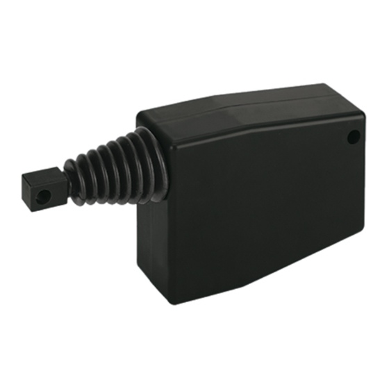
The electric cylinder is to be used exclusively for the adjustment of guided components or other adjustment tasks of a similar nature. The drive is carried out using the integrated DC motor. 6.2 Electric cylinder assembly M9 6.2.1 Dimensions Condensed water opening The plastic joint head is screwed onto the M8 thread of the push rod. -
Page 12: Characteristic Data Of The Basic Version
6. Product information 6.2.2 Characteristic data of the basic version Component Type M999 M999.1 M999.2 Standard electric connection 24 VDC Power consumption 15 Watt Dynamic tension and compression 300 N 125 N 300 N force Static tension and compression 500 N force Max. -
Page 13: Overview
6. Product information 6.2.4 Overview The electric cylinder of assembly M9 is available for 12 Volt and 24 Volt direct current. Housing cover Suspension front Bellows DC motor with Auger Tapped spindle Printed board with end switches Housing floor Cable 6.2.5 Lifting force and speed... -
Page 14: Switching Frequency
6. Product information 6.2.6 Switching frequency The electric cylinders of assembly M9 are not been suitable for continuous operation (100 per cent ED). The maximum number of double strokes per hour depending on the lifting force and lifting length are specified in the table. -
Page 15: Electric Cylinder Assemblies 010
6. Product information 6.3 Electric cylinder assemblies 010 6.3.1 Dimensions Lifting length setting Lifting length setting Lifting length setting Options: Bellows Bellows Protection class increases from IP40 to IP54 The fitting length can be adjusted ± 4 mm using the eyebolt. After setting, the eyebolt must be secured in place using the hexagon nut (see assembly accessories). -
Page 16: Characteristic Data Of The Basic Version
6. Product information 6.3.2 Characteristic data of the basic version Component Types LH10 LH11 LH950 Standard electric connection 24 VDC Power consumption 9 Watt 27 Watt Dynamic tension and 200 N 300 N 500 N compression force Static tension and compression 500 N 1250 N force... -
Page 17: Overview
6. Product information 6.3.4 Overview The electric cylinder of assembly 010 is available for 12 Volt and 24 Volt direct current. Front flange with Eyebolt DIN 444 Push rod Protective tube Tapped spindle Gear housing optimum sliding and gear bearing and scraper Shoulder flange* Adjustment spindle* DC motor... -
Page 18: Switching Frequency
6. Product information 6.3.6 Switching frequency The electric cylinders of assembly 010 are not been suitable for continuous operation (100 per cent ED). The maximum number of double strokes per hour depending on the lifting force and lifting length are specified in table I. With ambient temperatures of +20 °C or greater, the maximum permissible number of double strokes per hour is reduced. -
Page 19: End Position Limiting
6. Product information 6.3.7 End position limiting The electric cylinder must not be moved to the stop. Limit switches are installed as standard for limiting the end position. When commissioning, make sure that the electric cylinder is switched off in the end position electrically via the limit switch and that moving to the stop is prevented. -
Page 20: Other Options
6. Product information 6.3.9 Other options Bellows The electric cylinder of assembly 010 can be retrofitted with a bellows. The overall length and the fitting length extend by 30 mm as a result of this. With type M 10, the protection class increases from IP40 to IP54 with the bellows. Potentiometer The types LH10, LH11 and LH950 can be equipped with the following potentiometers: •... -
Page 21: Installation Position
6. Product information 6.3.11 Installation position The counter-piece must not be able to be twisted. The electric cylinder must be able to be rotated in the direction of the arrow (see graphic). 6.3.12 Other technical possibilities • Voltage, 12 VDC •... -
Page 22: Electric Cylinder Assemblies 015
6. Product information 6.4 Electric cylinder assemblies 015 6.4.1 Dimensions can be rotated by 90 deg. Push rod diam. 14 Cable length 1.5 m Basic version Module Standard lifting length: limit switch non-adjustable 140 mm 180 mm 300 mm Standard lifting length: limit switch adjustable 100 mm 140 mm 260 mm... -
Page 23: Characteristic Data Of The Basic Version
6. Product information 6.4.2 Characteristic data of the basic version Component Type lift (limit switch) LH15 LH15.1 LH15.2 LH15.6 LH15.7 LH15.8 non-adjustable Type lift adjustable LH15.3 LH15.4 LH15.5 LH15.9 LH15.10 LH15.11 Dynamic tension and compression 1000 N 600 N 300 N 450 N 200 N 60 N... -
Page 24: Overview
6. Product information 6.4.4 Overview The electric cylinder of assembly 015 is available for 12 Volt and 24 Volt direct current. Motor and screw Protective Front flange with Suspension Suspension Worm gear tube Tapped spindle Push rod Limit switch sliding bearing Gearbox front rear... -
Page 25: Switching Frequency
6. Product information 6.4.6 Switching frequency The electric cylinders of assembly 015 are not been suitable for continuous operation (100 per cent ED). The maximum switching frequency /h at +20 deg. Celsius ambient temperature is calculated as follows: Nominal lifting speed [mm/s] x560 [s/h] = [DH/h] Lifting path per double stroke [mm/DH]... -
Page 26: End Position Limiting
6. Product information 6.4.7 End position limiting The electric cylinder must not be moved to the stop. Limit switches are installed as standard for limiting the end position. When commissioning, make sure that the electric cylinder is switched off in the end position electrically via the limit switch, thus preventing it from moving to the stop. -
Page 27: Overrun After Switching Off And Repetition Accuracy
Information must be requested from the suppliers. 6.5 Limit switch The electric cylinders of the assemblies M9 / 010 / 015 are equipped with two limit switches. The limit switches prevent running over the maximum lifting length (extracted) as well as running over the lower retention point (retracted). -
Page 28: Life Phases
If a mains lead and/or feed line is damaged, the electric cylinder is to be taken out of service immediately. • Phoenix Mecano Komponenten AG does not accept any guarantees when the customer uses their own electric circuitry, exception is with a limit switch. -
Page 29: Installation
7. Life phases 7.4 Installation Check the electric cylinder for any damage after receiving it. The electric cylinder will be delivered read for operation without a controller. The following instructions must be observed during installation: • When using / mounting a joint head or fork head, make sure that the heads are secured correctly using the supplied nuts. -
Page 30: Cleaning
7. Life phases 7.6 Cleaning You can clean the hand switch and the outside surface of the electric cylinder's profile using a lint- free, clean cloth. Solvent-based cleaners will corrode the material and can damage it. 7.7 Disposal and return The electric cylinder must either be disposed of in accordance with the applicable regulations and guidelines, or returned to the manufacturer.
Need help?
Do you have a question about the M9 and is the answer not in the manual?
Questions and answers