Table of Contents
Advertisement
Quick Links
New Style Parallel Tank Connector
1. Read all instruc ons carefully before opera on.
2. Avoid pinched o‐rings during installa on by applying (provided with install kit) NSF cer fied lubri‐
cant to all seals.
3. This system is not intended for trea ng water that is microbiologically unsafe or of unknown
quality without adequate disinfec on before or a er the system.
REVISION #
0
REVISION DATE
02/19 54833-1
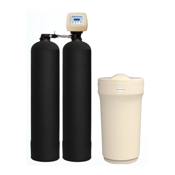
185HEDP
DUAL PASS Hardness
Reduc on System
Advertisement
Table of Contents

Related Manuals for WaterGroup 185HEDP


Summary of Contents for WaterGroup 185HEDP
- Page 1 185HEDP DUAL PASS Hardness Reduc on System New Style Parallel Tank Connector 1. Read all instruc ons carefully before opera on. 2. Avoid pinched o‐rings during installa on by applying (provided with install kit) NSF cer fied lubri‐ cant to all seals. 3. This system is not intended for trea ng water that is microbiologically unsafe or of unknown quality without adequate disinfec on before or a er the system. REVISION # REVISION DATE 02/19 54833-1...
-
Page 2: Unpacking Inspection
Table of Contents PAGE Unpacking / Inspection Safety Guide Proper Installation Specification Before Starting Installation Installation Instructions System Start Up Programming Instructions About The System Maintenance Sanitizing Procedure Main Repair Parts Trouble Shooting Warranty Unpacking / Inspection Be sure to check the entire softener for any shipping damage or parts loss. Also note dam- age to the shipping cartons. -
Page 3: Proper Installation
Proper Installation This water softening system must be properly installed and located in accordance with the Installation Instructions before it is used. Do not install or store where it will not be psi, night time pressure may exceed the exposed to temperatures below freezing or maximum. -
Page 4: Specifications
Specifications WG185HEDP-100 WG185HEDP-150 WG185HEDP-200 WG185HEDP-250 Specifica ons 2192-1 2193-1 2194-1 2195-1 Factory Se ngs Salt Used ‐ Per Regenera on 12.0 lbs 18.0 lbs 24.0 lbs 30.0 lbs Water Used ‐ Regenera on 86.4 gal 148 gal 162.4 gal 224.8 gal 30,000 45,000 60,000 75,000 Hardness Removal ‐ Grains Tank #1 Resin Quan ty ‐ Cubic Feet 1.0 1.50 2.0 2.5 Tank #2 Resin Quan ty ‐ Cubic Feet 1.0 1.50 2.0 ... -
Page 5: Where To Install The Softener
Where To Install The Softener Place the softener as close as possible to is least likely to occur if a leak develops. the pressure tank (well system) or water The manufacturer will not repair or pay for meter (city water). water damage. -
Page 6: Installation Instructions
Installation Instructions 1. If your hot water tank is electric, turn off the power to it to avoid damage to the element in the tank. 2. If you have a private well, turn the power off to the pump and then shut off the main wa- ter shut off valve. -
Page 7: Installation
Installation... -
Page 8: System Start-Up
System Start-Up Key Pad Configuration SETTINGS This func on is to enter the basic set up infor‐ ma on required at the me of installa on. MANUAL This func on is to ini ate an immediate or REGEN delayed manual regenera on. DOWN / Increase or decrease the value of the se ngs UP while in the programming mode. Manual Regeneration (Step / Cycle Valve) DELAYED REGENERATION IMMEDIATE REGENERATION Press and release the MANUAL REGEN. But- To start an immediate regeneration (or step ton to set a delayed regeneration that will valve through each position), press and hold... -
Page 9: Programming Instructions
Programming Instructions TIME DAY, YEAR, For SIM units choose IRON & MONTH, DAY, Time of day is for normal op- eration of system and the WATER TYPE scheduling of the regenera- Select WELL / OTHER if any tion time. The date is used Iron or Manganese is present in a diagnostic function to or if the water source is not... - Page 10 New Style Parallel Tank Connector The design of the parallel tank adaptor used in our dual-tank products (i.e. BIF/BAF, HTO, HEDP etc.) has been redeveloped. This new shorter version will also change the New flow directions. OUT— IN...
- Page 11 Regeneration Process Explained Backwash: Backwash: During the backwash cycle, water enters tank #2 through the center of the distribution tube and flows up- wards in the tank#2 expanding the media bed and carrying any precipitated contaminants trapped within the bed. It then travels to tank #1 through the center of the distribution tube and flow upwards in tank #1 and then out to the drain.
-
Page 12: Main Display
About The System Control Operation During A Power Failure In the event of a power failure, the valve will keep track of the time and day for 48 hours. The programmed settings are stored in a non-volatile memory and will not be lost during a power failure. -
Page 13: System Configuration
Precision Brining Regeneration Process When the system capacity is near exhausted, a regeneration is necessary to restore the sys- tem to full capacity. The table below explains the regeneration steps. Step Name Descrip on A precise calculated amount of fresh water is added to the brine tank to make enough brine to regenerate only the exhausted por on of the ion exchange #1 Brine Making resin. Note: 70% of the required fresh water is added in Step #5 in the previ‐ ous regenera on. The default brine making ... -
Page 14: Manual Bypass
Manual Bypass In the case of emergency, such as an overflowing brine tank, you can isolate your water softener from the water supply using the bypass valve located at the back of the control. In normal operation the bypass is open with the on/off knobs in line with the inlet and outlet pipes. - Page 15 Cleaning or Replacing Injectors Sediment, salt and silt will restrict or clog the injector. A clean water supply and pure salt will prevent this from happening. The injector assembly is located on the right side of the control valve. This assembly is easy to clean.
- Page 16 Replacing Brine Line Flow Control (BLFC) TIP: Markings on the BLFC washer should face the direction as shown here. 1. Remove the red clip that secures the brine elbow. 2. Remove the BLFC holder from the elbow fitting. 3. Split the BLFC holder apart and remove the flow washer. 4.
-
Page 17: Care Of Your System
Care of Your System To retain the attractive appearance of your new water softener, clean occasionally with mild soap solution. Do not use abrasive cleaners, ammonia or solvents. Never subject your sof- tener to freezing or to temperatures above 100°F. Resin Cleaner An approved resin cleaner must be used on a regular basis if your water supply contains iron. - Page 18 Brine Tank & Res-Up Feeder Assembly (Optional) Step 3 Install brine well. Feed wick from feeder into the opening in the brine well cap.
- Page 19 Main Repair Parts - Connectors...
-
Page 20: Control Valve Exploded View
Control Valve Exploded View VALVE REPAIR PARTS LIST Replacement Replacement Part Description Part Description Part Number Part Number 60010127 INJECTOR SET #0000 BLACK 60010129 85HE UPFLOW PISTON ASSEMBLY 60010126 INJECTTOR SET #000 GREY 60010171 85HE DOWNFLOW PISTON ASSEMBLY 60010035 INJECTOR SET #00 VIOLET 60010130 85HE SEAL & SPACER KIT 60010034 INJECTOR SET #0 RED 60010131 85HE DLFC #1 1.5 GPM 60010033 INJECTOR SET #1 WHITE 60010132 85HE DLFC #2 2.0 GPM 60010032 INJECTOR SET #2 BLUE 60010133 ... -
Page 21: Control Valve Parts List
Control Valve Parts List 185HE CONTROL VALVE (UPFLOW) Replacement MFG Part Number Part Description DWG # Quantity Part Number 5056087 Screw-M5x12(Hexagon) 5056088 Screw-M5x16(Hexagon With Washer) 5056047 End Plug Retainer 5031016 BNT85HE Piston Rod 5056097 Piston Pin 5031015 BNT85HE Quad Ring Plug Cover 5056070 Quad Ring 5031011... - Page 22 Power Head Exploded View...
-
Page 23: Power Head Parts List
Power Head Parts List 185HE POWER HEAD (UPFLOW) Replacement MFG Part Number Part Description DWG # Quantity Part Number 5056084 Screw-ST3.5X13 5010037 Screw-ST2.9X10 13000416 Screw-ST3.5X25 5031007 BNT85HE Piston Rod Guide Plate 5056510 Motor-12v/2rpm 5030014 Motor Power Cable 11700005 Wire Connector 5056098 Motor Pin 5031006... -
Page 24: Troubleshooting
Trouble Shooting... -
Page 25: Warranty
When properly installed and maintained, it will give years of trouble free service. Seven Year Complete Parts Guarantee WaterGroup will replace any part which fails within 84 months from date of manufacture, as indicated by the serial number, provided the failure is due to a defect in material or work- manship.
Need help?
Do you have a question about the 185HEDP and is the answer not in the manual?
Questions and answers