
Related Manuals for Electro-Automatik PS 3000 C Series


Summary of Contents for Electro-Automatik PS 3000 C Series
- Page 1 Operating Manual PS 3000 C DC Power Supply Attention! This document is only Doc ID: PS3EN valid for devices with firmwares “KE: 2.03”, “HMI: 2.02” and “DR: Revision: 02 2.0.1” or higher. Date: 04/2021...
-
Page 3: Table Of Contents
PS 3000 C Series TABLE OF CONTENTS GENERAL OPERATION AND APPLICATION About this document ........4 Personal safety ..........29 Operating modes .........29 1.1.1 Retention and use ..........4 3.2.1 Voltage regulation / Constant voltage ..29 1.1.2 Copyright ............4 3.2.2 Current regulation / constant current / current 1.1.3... -
Page 4: About This Document
PS 3000 C Series General About this document 1.1.1 Retention and use This document is to be kept in the vicinity of the equipment for future reference and explanation of the operation of the device. This document is to be delivered and kept with the equipment in case of change of location and/or user. -
Page 5: Disposal Of Equipment
PS 3000 C Series Disposal of equipment A piece of equipment which is intended for disposal must, according to European laws and regulations (ElektroG, WEEE) be returned to EA Elektro-Automatik for scrapping, unless the person operating the piece of equipment or another, delegated person is conducting the disposal. -
Page 6: Safety
PS 3000 C Series Safety 1.7.1 Safety notices Mortal danger - Hazardous voltage • Electrical equipment operation means that some parts will be under dangerous voltage. Therefore all parts under voltage must be covered! • All work on connections must be carried out under zero voltage (output not connected to a load which is also a voltage source) and may only be performed by qualified and informed persons. -
Page 7: Responsibility Of The Operator
PS 3000 C Series 1.7.3 Responsibility of the operator Operator is any natural or legal person who uses the equipment or delegates the usage to a third party, and is responsible during its usage for the safety of the user, other personnel or third parties. -
Page 8: Alarm Signals
PS 3000 C Series 1.7.5 Alarm signals The equipment offers various possibilities for signalling alarm conditions, however, not for danger situations. The signals may be optical (on the display as text) acoustic (piezo buzzer) or electronic (pin/status output of an analog interface). -
Page 9: Specific Technical Data
PS 3000 C Series 1.8.3 Specific technical data Model 160 W PS 3040-10 C PS 3080-05 C PS 3200-02 C AC supply Voltage range 90...264 V AC 90...264 V AC 90...264 V AC Connection Wall outlet Wall outlet Wall outlet... - Page 10 PS 3000 C Series Model 160 W PS 3040-10 C PS 3080-05 C PS 3200-02 C Power regulation Display: Resolution See section „1.9.5.4. Resolution of the displayed values“ Display: Accuracy ≤ 0,5% P ≤ 0,5% P ≤ 0,5% P Nenn...
- Page 11 PS 3000 C Series Model 320 W PS 3040-20 C PS 3080-10 C PS 3200-04 C AC supply Voltage range 90...264 V AC 90...264 V AC 90...264 V AC Connection Wall outlet Wall outlet Wall outlet Frequency 45-65 Hz 45-65 Hz...
- Page 12 PS 3000 C Series Model 320 W PS 3040-20 C PS 3080-10 C PS 3200-04 C Power regulation Display: Resolution See section „1.9.5.4. Resolution of the displayed values“ Display: Accuracy ≤ 0,5% P ≤ 0,5% P ≤ 0,5% P Nenn...
- Page 13 PS 3000 C Series Model 640 W PS 3040-40 C PS 3080-20 C PS 3200-10 C AC supply Voltage range 90...264 V AC 90...264 V AC 90...264 V AC Connection Wall outlet Wall outlet Wall outlet Frequency 45-65 Hz 45-65 Hz...
- Page 14 PS 3000 C Series Model 640 W PS 3040-40 C PS 3080-20 C PS 3200-10 C Power regulation Display: Resolution See section „1.9.5.4. Resolution of the displayed values“ Display: Accuracy ≤ 0,5% P ≤ 0,5% P ≤ 0,5% P Nenn...
-
Page 15: Views
PS 3000 C Series 1.8.4 Views Figure 1 - Front side Figure 2 - Rear side (320 W model sjhown) Do not loosen the grounding point (brass screw next to AC socket G) in order to connect PE cables! The device is supposed to be grounded via the AC cord, while the grounding point is used to connect the enclosure to PE. - Page 16 PS 3000 C Series Figure 3 - Side view from left, horizontal position (320 W model shown) Figure 4 - Top view (320 W model shown) EA Elektro-Automatik GmbH Fon: +49 2162 / 3785-0 www.elektroautomatik.com Page 16 Helmholtzstr. 31-37 • 41747 Viersen Fax: +49 2162 / 16230 ea1974@elektroautomatik.com...
-
Page 17: Control Elements
PS 3000 C Series 1.8.5 Control elements Figure 5 - Control Panel Overview of the elements on the control panel For a detailed description see section „1.9.5. The control panel (HMI)“ and „1.9.5.2. Rotary knobs“. Colour display Used for display of set values, menus, actual values, status and rotary knob assignment. -
Page 18: Construction And Function
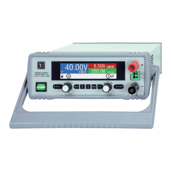
General description The laboratory power supply devices of PS 3000 C series are the third generation of small desktop units in the power class up to 640 W. Due to their compact size they’re especially suitable for research laboratories, test ap- plications or educational purposes. -
Page 19: Scope Of Delivery
PS 3000 C Series 1.9.3 Scope of delivery 1 x Power supply device 1 x USB stick with documentation and software 1 x Mains cord 1 x UK wall socket adapter 1.9.4 Optional accessories For these devices the following accessories are available: IF-KE5 USB Digital interface card with USB port. -
Page 20: The Control Panel (Hmi)
PS 3000 C Series 1.9.5 The control panel (HMI) The HMI (Human Machine Interface) consists of a display, two rotary knobs and six pushbuttons. 1.9.5.1 Display The graphic display is divided into a number of areas. In normal operation the upper part (⅔) is used to show actual and set values and thelower part (⅓) to display status information:... - Page 21 PS 3000 C Series • Status display (lower part) This area displays various status texts and symbols: Display Description The HMI is locked The HMI is unlocked Remote: The device is under remote control from..Analog ..the optional analog interface ..the optional USB port...
-
Page 22: Usb Port (Optional)
PS 3000 C Series 1.9.5.4 Resolution of the displayed values In the display, set values can be adjusted with a fixed step width. The number of decimal places depends on the device model. All values have 4 digits. Adjustment resolution of set values in the display:... -
Page 23: Analog Interface (Optional)
PS 3000 C Series 1.9.8 Analog interface (optional) On the rear side of the device there is a slot to install one out of three types of optionally available, user-retrofittable interface cards. Also see section 1.9.4. One of the types features an analog 15 pole D-Sub type connector, plus a USB port. -
Page 24: Installation & Commissioning
2.3.2 Preparation Mains connection for a PS 3000 C series device is done via the included 1.5 meters long 3 pole mains cord. Dimensioning of the DC wiring to the load has to reflect the following: • The cable cross section should always be specified for at least the maximum current of the device. - Page 25 PS 3000 C Series 2.3.3.1 The handle The included handle isn’t only used to carry the device, it can also uplift the device’s front for easier access to knobs and buttons or better display readability. The handle can be rotated into various positions in an angle of 300°, such as a variable position (60...150°), 0°, -45°, -90°...
-
Page 26: Connection To Dc Loads
PS 3000 C Series Standing surface (handle in -45° position) 2.3.4 Connection to DC loads • When using the model which is rated for 40 A, attention has to be paid to where the load is connected on the DC output terminals. The front 4mm banana plug hole is only rated for max. -
Page 27: Connection Of Remote Sensing
PS 3000 C Series 2.3.6 Connection of remote sensing • Remote sensing is only effective during constant voltage operation (CV) and for other regulation modes the sense input should be disconnected, if possible, because connecting it generally increases the oscillation tendency. -
Page 28: Connecting The Lan Port
PS 3000 C Series 2.3.9 Connecting the LAN port An Ethernet/LAN interface in form of a pluggable interface card is optionally available and can be retrofitted by the user on location into the rear side located slot. Connection to a remote host of any type (switch, server, PC) is done with standard Cat 5 Ethernet cables (patch cable, not included with the interface card). -
Page 29: Operation And Application
PS 3000 C Series Operation and application Personal safety • In order to guarantee safety when using the device, it’s essential that only persons operate the device who are fully acquainted and trained in the required safety measures to be taken when working with dangerous electrical voltages • For models which generate dangerous voltages, a protection against unwanted physical contact... -
Page 30: Current Regulation / Constant Current / Current Limitation
PS 3000 C Series 3.2.2 Current regulation / constant current / current limitation Current regulation is also known as current limiting or constant current mode (CC). The DC output current is held constant by the power supply, once the output current to the load reaches the adjusted limit. -
Page 31: Alarm Conditions
PS 3000 C Series Alarm conditions This section only gives an overview about device alarms. What to do in case your device indi- cates an alarm condition is described in section „3.6. Alarms and monitoring“. As a basic principle, all alarm conditions are signalled optically (text + message in the display) and acoustically (if activated), as well status and alarm counter readable via an optional, digital interface. -
Page 32: Manual Operation
PS 3000 C Series Manual operation 3.4.1 Powering the device The device should, as far as possible, always be switched on using the toggle switch on the front of the device. After switching on, the display will first show the company logo, followed by a language selection which will close automatically after 3 seconds and later manufacturer’s name and address, device type, firmware version(s), serial... - Page 33 PS 3000 C Series 3.4.3.1 Menu “Settings” This is main menu for all settings related to the general operation of the device and of the interface(s). Sub menu Description Output Settings Allows for adjustment of set values related to the DC output, alternatively to the...
- Page 34 PS 3000 C Series 3.4.3.3 Menu “Profiles” See „3.8 Loading and saving a user profile“ on page 45. 3.4.3.4 Menu “Overview” This menu page displays an overview of the set values (U, I, P or U, I, P, R) and alarm settings as well as adjust- ment limits.
- Page 35 PS 3000 C Series Sub menu Communication Protocols Element Description Enabled Default setting: SCPI&ModBus Enables/disables SCPI or ModBus RTU communication protocols for the device. The change is immediately effective after submitting it with Enter button. Only one of both can be disabled.
-
Page 36: Adjustment Limits
PS 3000 C Series 3.4.4 Adjustment limits Adjustment limits are only effective on the related set values, no matter if using manual adjust- ment or remote control! Defaults are, that all set values (U, I, P) are adjustable from 0 to 102%. -
Page 37: Switching The Main Screen View
PS 3000 C Series 3.4.6 Switching the main screen view The main screen, also called status page with its set values, actual values and device status, can be switched from the standard view mode with three values to a simpler mode. Refer to „3.4.3.7. Menu “HMI Setup”“ to see where to switch the view mode in the MENU. -
Page 38: Remote Control
PS 3000 C Series Remote control 3.5.1 General Remote control is possible via any of the optionally available, user-retrofittable interface cards (refer to „1.9.4. Optional accessories“) and their feature analog or digital interface port. Important here is that only one of both ports can be in control. -
Page 39: Remote Control Via The Analog Interface (Ai)
PS 3000 C Series 3.5.4 Remote control via the analog interface (AI) 3.5.4.1 General The optionally available, once installed built-in, galvanically isolated, 15-pole analog interface (short: AI) is located on the rear side of the device and offers the following possibilities: • Remote control of current, voltage and power... - Page 40 PS 3000 C Series 3.5.4.3 Acknowledging device alarms In case of a device alarm occurring during remote control via analog interface, the DC output will be switched off the same way as in manual control. The device would indicate all alarms (see 3.6.1) in the front display and some of them also as signal on the analog interface (see table below).
- Page 41 PS 3000 C Series 3.5.4.5 Overview of the Sub-D Socket 3.5.4.6 Simplified diagram of the pins Digital Input (DI) Analog Input (AI) V~0.5 The DI is internally pulled up and thus it High resistance input (impedance requires to use a contact with low resist- >40 k...
- Page 42 PS 3000 C Series • Remote control isn’t active In this mode of operation pin REM-SB can serve as lock, preventing the DC output from being switched on by any means. This results in following possible situations: Parameter Level „Analog on pin ...
-
Page 43: Alarms And Monitoring
PS 3000 C Series Alarms and monitoring 3.6.1 Device alarm and event handling A device alarm incident will usually lead to DC output switch-off, the appearance of a text message in the display and, if activated, an acoustic signal to make the user aware. -
Page 44: Control Panel (Hmi) Lock
PS 3000 C Series ► How to configure the alarm sound (also see “„3.4.3. Configuration via MENU“) While the DC output is switched off, press button In the menu navigate with the arrow buttons (↓, ↑) to Page 2 and press . -
Page 45: Loading And Saving A User Profile
PS 3000 C Series Loading and saving a user profile The menu Profiles serves to select between a default profile and up to 5 user profiles. A profile is a collection of all settings and set values. Upon delivery, or after a reset, all 6 profiles have the same settings and all set values are 0. -
Page 46: Other Applications
PS 3000 C Series Other applications 3.9.1 Series connection Series connection of two or multiple devices is basically possible, but for reasons of safety and isolation following restrictions apply: • Both, negative (DC-) and positive (DC+) output poles are coupled to PE via type X capacitors, limiting the max. -
Page 47: Service And Maintenance
PS 3000 C Series Service and maintenance Maintenance / cleaning The device needs no maintenance. Cleaning may be needed for the internal fans, the frequency of cleanse is depending on the ambient conditions. The fans serve to cool the components which are heated by the inherent high dissipation of energy. -
Page 48: Contact And Support
PS 3000 C Series Contact and support Repairs Repairs, if not otherwise arranged between supplier and customer, will be carried out by EA Elektro-Automatik. For this the equipment must generally be returned to the manufacturer. No RMA number is needed. It’s sufficient to package the equipment adequately and send it, together with a detailed description of the fault and, if still under guarantee, a copy of the invoice, to the following address. - Page 50 EA Elektro-Automatik GmbH & Co. KG Development - Production - Sales Helmholtzstraße 31-37 41747 Viersen Germany Fon: +49 2162 / 37 85-0 Mail: ea1974@elektroautomatik.com Web: www.elektroautomatik.com...
Need help?
Do you have a question about the PS 3000 C Series and is the answer not in the manual?
Questions and answers