
Related Manuals for ParaBody GS6-LP5A-101


Summary of Contents for ParaBody GS6-LP5A-101
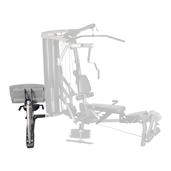
- Page 1 LEG PRESS ADAPTER KIT FOR GS6 GYM SYSTEM WARNING: Read and follow all directions for each step to insure proper assembly of this product. USER’S GUIDE CLASS H Version: GS6-LP5A-101 PART # 7363201 Revision: 11/01/02 REV. A...
- Page 2 3. Keep body and clothing free of all moving objects. DO NOT attempt to fix. Notify your authorized ParaBody dealer before use and have repairs made by 4. Inspect the machine before use. DO NOT use it if it an authorized service technician.
- Page 3 IMPORTANT NOTES Please note: * Thank you for purchasing the ParaBody GS6 Leg Press Adapter Kit. Please read these instructions thoroughly and keep them for future reference. This product must be assembled on a flat, level surface to assure its proper function.
- Page 4 ACU06-0024 3/8 X 4-3/4” BOLT ACU08-0076 ACUDA1E03843416NB STEP SPACER 1-19/32” NOTE: The LEG PRESS ATTACHMENT (LP5) must be assembled before connecting it to the PARABODY GS6 GYM SYSTEM FIGURE 1 BASE 10 3/8 X 3-3/4” 3/8 X 3-3/4” 10 LEG PRESS STEP 1: •...
- Page 5 BASE 10 3/8 X 3-3/4” FIGURE 2 STEP 2: • Install the PULLEY HOUSING (3) to the BASE using two 3/8 X 3-3/4” BOLTS (10) and two 3/8” LOCK NUTS (14) as shown in FIGURE 2 FIGURE 3 LAT CABLE DISCARD! STEP 3: •...
- Page 6 3/8 X 3-3/4” 10 3/8 X 1-3/4” 12 TOP PLATE ASSEMBLY FRONT FRAME FIGURE 4 STEP 4: • Screw the threaded end of the new LAT CABLE (6) into the end of the HEAD PLATE ASSEMBLY. • SECURELY assemble one 3-1/2 PULLEY (8) to the FLOATING PULLEY BRACKET (2) using one 3/8 X 1-3/4” BOLT (12) and one 3/8” LOCK NUT (14) as shown in FIGURE 4.
- Page 7 FIGURE 5 12 3/8 X 1-3/4” STEP 5: • Screw the threaded end of the LEG PRESS CABLE (7) into the end of the FLOATING PULLEY BRACKET (2) as shown in FIGURE 5. • Assemble one 3-1/2 PULLEY (8) to the PULLEY HOUSING (3) using one 3/8 X 1-3/4” BOLT (12) and one 3/8” LOCK NUT (14) as shown in FIGURE 5.
- Page 8 FIGURE 6 SEAT FRAME BRACKET 12 3/8 X 1-3/4” STEP 6: • Carefully route the LEG PRESS CABLE (7) around one 3-1/2” PULLEY (8) and SECURELY assemble the 3-1/2” PULLEY (8) to the BRACKET (from the LP5 LEG PRESS) using one 3/8 X 1-3/4” BOLT (12), one 3/8” WASHER (13), one CABLE RETAINER (5) and one 3/8”...
- Page 9 SEAT FRAME BRACKET 3/8 X 4-3/4” FIGURE 7 STEP 7: • SECURELY attach the BRACKET (from LP5 LEG PRESS) to the SEAT FRAME using two 3/8” X 4-3/4” BOLTS (9), two 3/8” WASH- ERS (13), and two 3/8” LOCK NUTS (14). See FIGURE 7. FIGURE 8 3/8 X 1-3/4”...
- Page 10 FIGURE 9 SEAT FRAME 3/8 X 4-3/4” 9 STEP 9: • Carefully route the LEG PRESS CABLE (7) around one 3-1/2” PULLEY (8) and SECURELY assemble the 3-1/2” PULLEY (8) to the SEAT FRAME using one 3/8 X 4-3/4” BOLT (9), two 1-19/32” STEP SPACERS (18) and one 3/8” LOCK NUT (14) as shown in FIGURE 9. Make sure the CABLE is in the grooves of all the pulleys.
- Page 11 FIGURE 11 SEAT FRAME 3/8 X 4-3/4” 9 STEP 11: • SECURELY assemble the swivel end of the LEG PRESS CABLE (7) to the SEAT FRAME using one 3/8 X 4-3/4” BOLT (9), two 1-11/16” STEP SPACERS (17) and one 3/8” LOCK NUT (14). (NOTE: SECURELY tighten, then back nut off 1/4 turn) CABLE ROUTING DIAGRAM...
- Page 12 HEAD PLATE from lifting up. • If further CABLE ADJUSTMENT is needed, reference the GS6 GYM SYSTEM assembly instructions. THIS CONCLUDES THE ASSEMBLY OF THE GS6-LP5A-101 LEG PRESS ADAPTER KIT...
Need help?
Do you have a question about the GS6-LP5A-101 and is the answer not in the manual?
Questions and answers