Panasonic EH-NE83 Service Manual
Hide thumbs
Also See for EH-NE83:
- Operating instructions manual (36 pages) ,
- Operating instructions manual (52 pages)
Advertisement
Quick Links
TABLE OF CONTENTS
1 Warning ---------------------------------------------------------------------------------------
2 Specifications ------------------------------------------------------------------------------- 2
3 Troubleshooting Guide ------------------------------------------------------------------------ 3
4 Disassembly and Assembly Instructions -------------------------------------------- 5
5 Wiring Connection Diagram------------------------------------------------------ 12
6 Schematic Diagram ---------------------------------------------------------------- 15
7 Exploded View & Replacement Parts List ----------------------------------- 16
Order Number PEWT1710A28CE
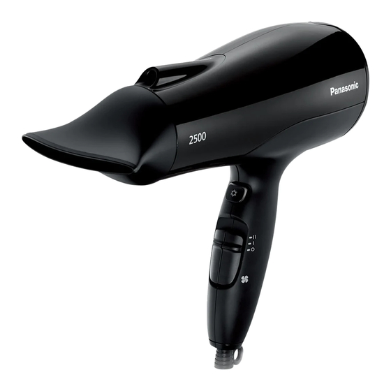
(Household) Hair Dryer
EH-NE83
Model No.
Asia
Middle East
PAGE
2
2
3
5
12
13
15
© Panasonic Corporation 2013 Unauthorized copying
and distribution is a violation of law.
Advertisement

Related Manuals for Panasonic EH-NE83


Summary of Contents for Panasonic EH-NE83
-
Page 1: Table Of Contents
3 Troubleshooting Guide ------------------------------------------------------------------------ 3 4 Disassembly and Assembly Instructions -------------------------------------------- 5 5 Wiring Connection Diagram------------------------------------------------------ 12 6 Schematic Diagram ---------------------------------------------------------------- 15 7 Exploded View & Replacement Parts List ----------------------------------- 16 © Panasonic Corporation 2013 Unauthorized copying and distribution is a violation of law. -
Page 2: Warning
1. Warning Caution: - Pb free solder has a higher melting point that standard solder; Typical the melting point is 50 - 70°F (30 - 40℃) higher. Please use soldering iron with temperature control and adjust it to 750 ±20°F (400 ± 10 ℃). In case of using high temperature soldering iron, please becareful not to heat too long. -
Page 3: Troubleshooting Guide
3. TROUBLESHOOTING GUIDE Refer to WIRING CONNECTION DIAGRAM. < TROUBLE > < REMEDY > < CHECK > <CHECK TEMPERATURE SWITCH> Replace the Check the conductivity between the terminal 2 Hot air is not emitted MAIN SWITCH and 4 by setting the TEMPERATURE SWITCH to Position 2 (Figure 1) Lead Wire (Black) - Page 4 3. TROUBLESHOOTING GUIDE Refer to WIRING CONNECTION DIAGRAM. < TROUBLE > < REMEDY > < CHECK > Main body is <CHECK POWER CORD> Replace the not operated Check the conductivity of power cord MOTOR HEATER ASSEMBLY Replace the <CHECK MAIN SWITCH> MAIN SWITCH Check the conductivity between the terminal 1 and 4 by setting...
-
Page 5: Disassembly And Assembly Instructions
4. Disassembly and Assembly Instructions 4.1. Disassembly Instructions 1. Remove the FILTER FRAME ASSEMBLY 4. Remove TAPPING SCREWS by a cross slot screw driver.Than take out AIR OUTLET RING and AIR OUTLET GRILL by rotating follow the direction below. 2. Remove 3 TAPPING SCREWS by a cross slot screw driver,then Remove AIR INLET RING. - Page 6 4. Disassembly and Assembly Instructions 4.1. Disassembly Instructions 7. remove Ion Holder from DISCHARGE COVER as figure below. Unclip this 2 ribs 8. Take off MOTOR HEATER ASSEMBLY, and PLATE SPRING from HOUSING B.
- Page 7 4.2 Assembly Instructions 1. High voltage lead wire for Ion discharge must be fixing with Ribs from Heater holder as below picture.
- Page 8 2. Install MAIN SWITCH PLATE AB and MAIN SWITCH HOLDER. Ribs of MAIN SWITCH HOLDER must fully lock with MAIN SWITCH (2 Ribs) 3. Install Ion discharge in to DISCHARGE COVER.
- Page 9 4. Assemble MOTOR HEATER ASSEMBLY, COOL SWITCH PLATE and PLATE SRPING into HOUSING B. Position of component must be as below Lead wire to Heater block assembly must not on this area (EH-NE81,82,83,84 only)
- Page 10 5. Assemble DISCHARGE COVER / DESIGN COVER into HOUSING B. 6. Assemble HOUSING A, then tightening 2 TORX SCREWS. TORX SCREWS 3.0*12 7. Assemble AIR INLET RING and 3 TAPPING SCREWS. TAPPING SCREWS 2.6*10...
- Page 11 8. Install a AIR OUTLET GRILL into AIR OUTLET RING. Then install in to MAIN BODY with TAPPING SCREW. clockwise rotation TAPPING SCREW 2.0*4.0 9. Install a FILTER FRAME ASSEMBLY.
-
Page 12: Wiring Connection Diagram
5. Wiring Connection Diagram... -
Page 13: Schematic Diagram
6. Schematic Diagram SW1 (Main Switch) SW1 (Temperature Switch) SW2 (Cool Switch) 11-12 Main Sw. Temp Sw. Cool Sw. Cool mode Healthy mode (EH-NE81,83,N2500) Sensor mode (EH-NE82,84) Hot mode Symbol Part name Specification FCHW1, 11.5 W/m RHA, RHB Resistance Wire A, B FCHW1, 7.13 W/m Resistance Wire C NCHW2, 21.29 W/m... -
Page 14: Exploded View & Replacement Parts List
7. EXPLODED VIEW & REPLACEMENT PARTS LIST 7.1. Exploded View for : EH-NE83 All parts are supplied from PMFTH-AP through PLAP... - Page 15 7.2 Parts List for EH-NE83 Safety Ref. No. Part No. Part Name & Description Q'ty Remarks EHNE83SNZBW SET NOZZLE (BLACK) EHNE83DCBW DISCHARGE COVER (BLACK) EHNE83AORBW AIR OUTLET RING (BLACK) EHNE83AIRBW AIR INLET RING (BLACK) EHNE83CSBBW COOL SWITCH BUTTON (BLACK) EHNE83MHB2W...
Need help?
Do you have a question about the EH-NE83 and is the answer not in the manual?
Questions and answers