
Related Manuals for JF JF 40P


Summary of Contents for JF JF 40P
- Page 1 OPERATION TECHNICAL MANUAL MANUAL TÉCNICO DE OPERACIÓN Í C O I N A M Á JF 40P FORAGE CHOPPER - ENSILADORA Rev. 00...
- Page 3 OPERATION TECHNICAL MANUAL - FORAGE CHOPPER JF 40P 1 - Introduction Congratulations! You have just purchased an excellent forage chopper, easy to operate and maintain and ideal to assist yours silage needs. We thank you for choice of a machine really suitable to your needs, which is made by a company that continuously searches for the improvement of its products.
-
Page 4: Table Of Contents
2 - Illustrations in this Manual are merely illustrative. 3- JF offers one free operation training at the factory. Contact JF Training Department and ask for further information. -
Page 5: 2- Safety Recommendations
OPERATION TECHNICAL MANUAL - FORAGE CHOPPER JF 40P 2- Safety Recommendations Observe the recommendations of your Tractor's Manual, for a safe and efficient operation. 2.1- While Reading the Manual Note: It means that a detail will be presented and it may concerns operation or security. -
Page 6: When Operating The Forage Chopper
2.2- When operating the Forage Chopper 1- The Forage Chopper JF 40P has been developed exclusively to chop forages to animal food. 2- When supply the machine, never introduct the hands into the feeding chute (1). 3- In order to obtain the maximum efficiency and quality of chopped material, maintain a constant and uniform feeding. -
Page 7: 3- Machine Presentation
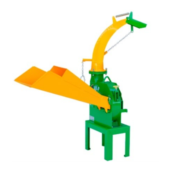
OPERATION TECHNICAL MANUAL - FORAGE CHOPPER JF 40P 3- Machine presentation 3.1- Parts identification 1- Feeding nozzle. 2- Rotary discharge tube. 3- Deflector. 4- Chopper (2 knifes). 5- Rack (to machine and driving motor). 6- Rubber cushions (4 units). 7- Pulley with two channel (1 unit). -
Page 8: Operation
3.2- Operation The Forage Chopper JF 40P has simple and efficient running. It is designed to chop corn, sugar cane, sorghum, elephant grass etc., as much to make silage as to daily ration. The product is inserted through the feeding nozzle (1). In the machine housing the impeller (2) chop the product and throw out the particles from the chute (3). -
Page 9: Technical Specifications
OPERATION TECHNICAL MANUAL - FORAGE CHOPPER JF 40P 3.3- Technical specifications Drive ....................... Electric motor Power of the motor ............... 7,5 hp to 10 hp (5,5 to 7,5 kw) Work speed .................... 2.400 to 2.600 rpm Cutting knives ......................3 units Driving belt ........................ -
Page 10: 4- Assembly And Adjustments Before Operating
4- Assembly and adjustments before operating 4.1- Assembly of the detached parts The parts described below are delivered disassembled to facilitate the machine transport. Assemble it according next steps: Feeding nozzle (1) Install the feeding nozzle (1) according picture aside and fasten it through pin (1a) and cotterpin (2b), which are together with the detached items that follow the machine. - Page 11 OPERATION TECHNICAL MANUAL - FORAGE CHOPPER JF 40P Rack (3) If the rack (3) is disassembled, assemble it according next steps. a) Assemble the rubber cushion (3a) according detail below, using the bolts (3b) + plain washer + spring washer + nut.
- Page 12 Installing the Forage Chopper and motor on the rack Forage Chopper Install the Forage Chopper on the rack (3) and fasten it with four bolts (4a) + plain whashers and the nuts. Electric motor IMPORTANT: See required motor power on page 9. Install the motor on the rails (3c) and fasten it with the bolts (4b) + plain washers and nuts.
- Page 13 OPERATION TECHNICAL MANUAL - FORAGE CHOPPER JF 40P Assemble the belts and the motor pulleys Pulley (5) a) Remove front cover (5a) releasing four nuts (5b - two upper and two under). b) Install the pulley (5) on motor axle with one key.
- Page 14 Belts (6) IMPORTANT: Use a pair of belts A55. a) Install the belts (6) as ilustrated aside. NOTE: If necessary displace the motor lenghwise (see arrows aside) to assemble the belts, see instructions in this manual. b) Adjust the belt tightening according instructions in this manual.
-
Page 15: Forage Chopper Adjustments
OPERATION TECHNICAL MANUAL - FORAGE CHOPPER JF 40P 4.2- Forage Chopper adjustments When you operate the Forage Chopper, adjust the chute position (1) and the deflector (2) according next steps: Chute (1) Turn the chute manually according desired position. If necessary, release the nuts (1a) to turn the chute easily. -
Page 16: 5- Step By Step Operation
5- Step by step operation a) Turn the chute (1) to the desired direction, according instructions on previous page. b) Adjust the deflector position (2) according instructions on previous page. c) Turn the machine on. d) Put the product on feeding nozzle (3) on continuously way as possible and in quantity compatible with the machine and feeding nozzle capacity. -
Page 17: 6- Maintenance Instructions
OPERATION TECHNICAL MANUAL - FORAGE CHOPPER JF 40P 6- Maintenance instructions 6.1- Grease lubricating points Lubricate each 8 work hours or daily the rear and frontal bearings chopper (see pictures below), using a grease pump. Recommended grease Lithium soap base grease Grade 2. -
Page 18: Chopper Knives Sharpening
6.2- Chopper knives sharpening This operation is more important on machine maintenance, because aim at good performance and durability of the knives (1). The sharpeness should be made in such a way to preserve the characteristics of the knives and the tempering of the steel. -
Page 19: Gap Adjustments Between Knife And Counterknife
OPERATION TECHNICAL MANUAL - FORAGE CHOPPER JF 40P e) Let the impeller (4) locked with a wood shim and Chanfer reinstall the knifes (1), observing the correct fastening position: the face with the chamfer should be returned for the rear of the Forage Chopper, according to picture aside. -
Page 20: Counterknife
6.4- Counterknife If the counterknife (1) is worn, with the edge rounded, invert it to use the other side. IMPORTANT: The counterknife has four operation edges (positions) (A, B, C and D), according ilustrated below: Transversal section of the counterknife (1) When all sides are worn (rounded), replace it. -
Page 21: Belts Tension Adjustment And Replacements
OPERATION TECHNICAL MANUAL - FORAGE CHOPPER JF 40P 6.5- Belts tension adjustment and replacements Check the belt tension (1) every 50 work hours or weekly. To do it: a) Remove front cover (5a) loosing the four nut (3 - two upper and two lower). -
Page 22: Forage Chopper Preservation
6.6- Forage Chopper preservation Protect the machine against bad weather and the corrosive effect of some products. After the use, adopt the cares below: Remove all product waste that remainded inside the machine. Always if necessary, wash the machine and let it dry at the sun. Check the bolts tightener of the impeller knifes. -
Page 23: 7- Machine Work Speed Adjustment
OPERATION TECHNICAL MANUAL - FORAGE CHOPPER JF 40P 7- Machine work speed adjustment See on page 9 the speed ratio to operate the JF 40P. To have diferent speeds in this zone. Its necessary change the pulleys combination, that is, use diferents diameters. -
Page 24: 8- Stickers Found On The Forage Chopper
8- Stickers found on the Forage Chopper... -
Page 25: 9- Detached Items That Come Along With The Forage Chopper
OPERATION TECHNICAL MANUAL - FORAGE CHOPPER JF 40P 9- Detached items that come along with the Forage Chopper Identification Especification Quantity Output chute 1 unit Feeding nozzle 1 unit Feeding nozzle pin 1 unit 2 units Assembled rack 1 unit... -
Page 26: 10- Troubleshooting
10- Troubleshooting Problem Causes Solution Excessive machine The machine is not on a Put the machine on a vibration. proper base. leveled and rigid base. The impeller is unbalanced. Check the quantity, assembled position and knife weight. Machine has chocked. Open the cover of the impeller compartment and remove the accumulated... -
Page 27: 11- Technical Assistance
OPERATION TECHNICAL MANUAL - FORAGE CHOPPER JF 40P 11- Technical assistance 11.1- Machine serial number The Forage Chopper JF 40P is identified with a serial number, located on plate (1) fixed in the machine casing. Write here the serial number of your Forage chopper:... -
Page 28: Warranty Term
Warranty Term The Agricultural Equipment described in this manual is guaranteed by JF Máquinas Agrícolas Ltda. for a period of 01 (one) year from the puchase bill issue date to the first owner/consumer of this product, confirmed through the Technical Delivery Voucher. -
Page 29: Technical Delivery Receipt
6 – Has a step-by-step description of the operation been explained? ( ) Yes ( ) No ( ) Yes ( ) No Technical Delivery Responsible Signature Customer/Owner Signature Delivery Date Technical Delivery Receipt Second Copy: JF Factory Owner: Telephone: Address: City: State: Owner E-mail Address: Equipment Type: Serial Number:... - Page 30 If the retailer has not done the Technical Delivery, just fill in the header. After filling in (partially or totally), the customer must keep this copy. If the retailer has not done the Technical Delivery, just fill in the header. After filling in (partially or totally), forward this second copy of the Report to the After Sales Department to the address that is on the back cover of this Manual.
- Page 31 MANUAL TÉCNICO DE OPERACIÓN - ENSILADORA JF 40P 1 - Introducción Felicitaciones! Usted ha adquirido una máquina con mantenimiento y operación muy sencilla, ideal para atender sus necesidades de ensilaje. Agradecemos por haber elegido una máquina realmente adecuada a sus necesidades, fabricada por una empresa que busca incesantemente mejorar sus productos.
- Page 32 2- Las ilustraciones contenidas en este manual son meramente ilustrativas. 3- JF pone a su disposición un entrenamiento gratuito de operación en la fábrica. Entre en contacto con el departamento de entrenamiento de JF y solicite...
-
Page 33: 2- Recomendaciones De Seguridad
MANUAL TÉCNICO DE OPERACIÓN - ENSILADORA JF 40P 2- Recomendaciones de Seguridad Observa también las recomendaciones del Manual de su tractor, para una operación segura y eficiente. 2.1- Al leer el Manual de Instrucciones Notas: Significa que será presentado un detalle, que podrá ser operacional o de seguridad. -
Page 34: Al Operar La Ensiladora
2.2- Al operar la Ensiladora 1- La Ensiladora JF 40P fue desarollada exclusivamente para picar forraje para alimentación animal. 2- Al alimentar la máquina, nunca introduzca las manos en la boquilla de alimentación (1). 3- Para garantizar el máximo rendimiento y calidad del material picado, mantenga una alimentación constante... -
Page 35: 3- Presentación De La Ensiladora
MANUAL TÉCNICO DE OPERACIÓN - ENSILADORA JF 40P 3- Presentación de la Ensiladora 3.1- Identificación de los componentes 1- Boquilla de alimentación 2- Boquilla giratoria de salida 3- Deflector 4- Rotor picador (2 cuchillas) 5- Caballete (para la máquina y el motor de accionamiento) -
Page 36: Principio De Funcionamiento
3.2- Principio de funcionamiento La Ensiladora JF 40P posee un funcionamiento sencillo y eficaz. Ella ha sido desarrollada para picar maíz, caña de azucar, sorgo, pasto etc., tanto para hacer forraje como para el diario. El producto es introducido por la boquilla de alimentación (1). Dentro de la máquina, el rotor (2) pica el producto y arroja las partículas por la boquilla de salida (3). -
Page 37: Especificaciones Técnicas
MANUAL TÉCNICO DE OPERACIÓN - ENSILADORA JF 40P 3.3- Especificaciones técnicas Accionamiento ....................Motor eléctrico Potencia necesaria del motor ..........7,5 cv a 10 cv (5,5 a 7,5 kw) Rotación de trabajo ................. 2.400 a 2.600 rpm Cuchillas de corte ....................3 unidades Correa de accionamiento .................... -
Page 38: 4- Montajes Y Ajustes Antes De La Operación
4- Montajes y ajustes antes de la operación 4.1- Montaje de piezas sueltas Las piezas que se describen a continuación son entregadas desmontadas, para facilitar el transporte de la máquina. Realice el ensamble según la descripción: Boquilla de alimentación (1) Ensamble la boquilla de alimentación (1) según la figura al lado, fijándola con el perno (1a) y los dos pasadores (1b) que hacen parte de las piezas sueltas que... - Page 39 MANUAL TÉCNICO DE OPERACIÓN - ENSILADORA JF 40P Caballete (3) Si el caballete (3) ha venido desmontado, realice el ensamble como se describe: a) Monte los 4 amortiguadores de goma (3a) según el detalle a continuación, usando para cada uno de ellos un tornillo (3b), más arandela lisa, más arandela de...
- Page 40 Montaje de la ensiladora y del motor sobre el caballete Ensiladora Coloque la ensiladora sobre el caballete (3) y fíjela con los 4 tornillos (4a), más arandelas lisas, más las tuercas que acompañan la máquina. Motor eléctrico IMPORTANTE: Vea la potencia necesaria del motor en la página 9.
- Page 41 MANUAL TÉCNICO DE OPERACIÓN - ENSILADORA JF 40P Montaje de la polea del motor y de las correas Polea (5) a) Quite la parte frontal de la cubierta (5a) aflojando las 4 tuercas mariposa (5b - dos arriba y dos abajo).
- Page 42 Correas (6) IMPORTANTE: Use un par de correas A55. a) Monte las correas (6) según la figura al lado. OBS.: Si fuese necesario desplazar el motor hacia adelante o hacia atrás (vea las flechas al lado) para montar las correas, consulte las instrucciones en este manual.
- Page 43 MANUAL TÉCNICO DE OPERACIÓN - ENSILADORA JF 40P 4.2- Ajustes de la Ensiladora Antes de operar la ensiladora, ajuste la posición de la boquilla de salida (1) y del deflector (2) según se describe a continuación: Boquilla (1) Gire manualmente la boquilla según la posición deseadas para la descarga del producto.
-
Page 44: 5- Operación Paso A Paso
5- Operación paso a paso a) Gire la boquilla de salida (1) hacia la dirección deseada, según instrucciones de la página anterior. b) Ajuste la posición del deflector (2) según instrucciones de la página anterior. c) Prenda la máquina. d) Alimente la máquina por la boquilla (3) de la forma más continuada posible y en cantidades compatible con la capacidad de la máquina y con la boquilla de entrada. -
Page 45: 6- Instrucciones De Mantenimiento
MANUAL TÉCNICO DE OPERACIÓN - ENSILADORA JF 40P 6- Instrucciones de mantenimiento 6.1- Puntos de lubricación con grasa Lubrique a cada 8 horas de trabajo o diariamente los cojinetes traseros y delantero del rotor picador (vea las figuras abajo), usando una engrasadora. -
Page 46: Afilado De Las Cuchillas Del Rotor Picador
6.2- Afilado de las cuchillas del rotor picador Esta es la operación más importante en el mantenimiento de la máquina, pues mantiene el buen desempeño y durabilidad de las cuchillas (1). El afilado debe ser hecho de manera a conservar las caracteristicas del perfil de las cuchillas y el templado del acero. -
Page 47: Ajuste De La Distancia Entre Las Cuchillas Y Contracuchilla
MANUAL TÉCNICO DE OPERACIÓN - ENSILADORA JF 40P e) Mantenga el rotor (4) calzado con el calce de madera y Bisel vuelva a instalar las cuchillas (1), observando la posición de fijación de las mismas: el lado con el bisel debe quedar hacia la parte de atrás de la ensiladora,... - Page 48 6.4- Contracuchilla Si la contracuchilla está con desgaste, con el borde redondo, girela para aprovechar otor borde. IMPORTANTE: La contracuchilla posee 4 bordes (posiciones) de uso (A, B, C y D), según se muestra en la figura abajo: Sección transversal de la contracuchilla (1) Cuando todos los bordes de la contracuchilla se encuentran gastos (redondos), reemplácela.
-
Page 49: Ajuste De La Tensión Y Cambio De Las Correas
MANUAL TÉCNICO DE OPERACIÓN - ENSILADORA JF 40P 6.5- Ajuste de la tensión y cambio de las correas Controle el huelgo de las correas (1) a cada 50 horas de trabajo, o semanalmente. Para ello: a) Quite la parte frontal de la cubierta (2) aflojando las cuatro tuercas (3 - dos arriba y dos abajo). -
Page 50: Conservación De La Ensiladora
6.6- Conservación de la Ensiladora Proteja siempre la Ensiladora de la intemperie y de los efectos corrosivos de algunos productos. Tras el uso, adote los cuidados a continuación: Quite todos los residuos de producto que hayan restando en el interior de la ensiladora. Siempre que sea necesario, limpie bien limpia la máquina por dentro y por fuera. -
Page 51: 7- Ajuste De La Rotación De Trabajo De La Máquina
7- Ajuste de la rotación de trabajo de la máquina Vea en la página 9 la gama de rotación ideal para operar la JF 40P. Para obtener diferentes rotaciones dentro de ésta gama, es necesario alterar la combinación de poleas, o sea, usar diámetros diferentes. -
Page 52: 8- Calcomanías Encontradas En La Máquina
8- Calcomanías encontradas en la Máquina... -
Page 53: 9- Piezas Sueltas Que Acompañan La Ensiladora
MANUAL TÉCNICO DE OPERACIÓN - ENSILADORA JF 40P 9- Piezas sueltas que acompañan la Ensiladora Identificación Especificación Cantidad Boquilla de salida 1 unidad Boquilla de alimentación 1 unidad Perno de la boquilla de alimentación 1 unidad Pasador 2 unidades Caballete montado... -
Page 54: 10- Diagnóstico De Anormalidades E Soluciones
10- Diagnóstico de anormalidades e soluciones Anormalidad Causas Solución Máquina con vibración La máquina no está sobre Coloque la máquina sobre excesiva. una base adecuada. una base nivelada y firme. El rotor no está balanceado. Verifique la cantidad, posición de montaje y peso de las cuchillas. -
Page 55: 11- Asistencia Técnica
MANUAL TÉCNICO DE OPERACIÓN - ENSILADORA JF 40P 11- Asistencia Técnica 11.1- Número de serie de la Ensiladora La Ensiladora JF 40P es identificada con un número de serie, el cual consta en la placa (1) fijada en la carcasa de la máquina. -
Page 56: Término De Garantía
Término de Garantía El equipo agrícola descrito en este manual es garantizado por JF Máquinas Agrícolas LTDA. por un período de 01 (un) año a partir de la fecha de emisión de la nota fiscal de venta al primer propietario / consumidor de este producto, confirmado a través del Comprobante de Entrega Técnica. -
Page 57: Comprobante De Entrega Técnica
( ) No ( ) Si ( ) No Firma del responsable por la Entrega Técnica Firma del propietario / Cliente Fecha de entrega Comprobante de Entrega Técnica 2 Copia: Fábrica JF Propietario: Teléfono: Dirección: Ciudad: E-mail Propietario: Mod. Equipo: Nº... - Page 58 Caso el no haya realizado la Entrega Técnica, llenar apenas el encabezado. Después del llenado (parcial o total), el cliente debe guardar esa copia. Caso el revendedor no haya realizado la Entrega Técnica llenar apenas el encabezado. Después del llenado (parcial o total), encamine esa copia del Formulario al Departamento de Postventas, conforme la dirección en la contraportada de este manual.
- Page 60 THE SOLUTION FOR THE PRODUCER LA SOLUCIÓN PARA EL PRODUCTOR JF Máquinas Agrícolas Ltda CNPJ: 46.127.635/0001-55 Address / Dirección ............. Rua Santa Terezinha, Nº921. Jd. Guarujá - Itapira - SP - Brasil Cep: 13973-900 Post Sale Department Caixa Postal: 114.
Need help?
Do you have a question about the JF 40P and is the answer not in the manual?
Questions and answers