
Related Manuals for JF 1000 AT


Summary of Contents for JF 1000 AT
- Page 1 MANUAL DE INSTRUCCIONES OPERATION TECHNICAL MANUAL JF 1000 AT CABEZAL DE ÁREA TOTAL / ROW INDEPENDENT HEAD...
- Page 3 JF 1000-AT Sr. Propietario Felicitaciones por la compra del Cabezal de Área Total JF 1000-AT, un producto de la más alta calidad, especialmente desarrollado para atender sus necesidades. E s t e m a n u a l c o n t i e n e i n s t r u c c i o n e s d e operación, mantenimiento y seguridad, que si...
-
Page 4: Table Of Contents
Manual de Instrucciones ÍNDICE Índice ..............................4 Identificación............................5 Medio ambiente ........................... 5 Precauciones de seguridad ......................... 6 Seguridad general ..........................6 Seguridad en la preparación ....................... 7 Seguridad de operación ........................8 Seguridad en el mantenimiento ......................9 Seguridad en el transporte ........................ 10 Seguridad personal ........................... -
Page 5: Identificación
JF 1000-AT IDENTIFICACIÓN Su Cabezal es identificada con número de serie, ubicado en la plaqueta fijada en el cuerpo de la máquina. Anote aquí el nº de serie de su máquina: IMPORTANTE! Al enviar comunicaciones o solicitar auxilio de la Asistencia Técnica, siempre informe el número de... -
Page 6: Precauciones De Seguridad
Manual de Instrucciones CUIDADO! PRECAUCIONES DE SEGURIDAD A palavra “CUIDADO” indica situações onde há risco oculto em potencial, cujas consequências, El operador de la máquina debe se não evitadas, podem ocasionar lesões graves. familiarizarse con los procedimientos de operación y mantenimiento y PELIGRO! la información de SEGURIDAD relacionada, que consta en este... -
Page 7: Seguridad En La Preparación
JF 1000-AT ƒ Fije los extremos de las protecciones de los SEGURIDAD EN LA cardanes en puntos fijos del tractor y del PREPARACIÓN implemento, a través de las cadenas específicas ƒ Asegúrese que la máquina para esta finalidad, para que las mismas esté... -
Page 8: Seguridad De Operación
Manual de Instrucciones ƒ No permita que niños o curiosos se aproximen SEGURIDAD DE OPERACIÓN de la máquina durante la operación o maniobras. ƒ No opere la máquina en el caso ƒ Mantenga todas las defensas y protecciones de que haya ingerido bebida en sus debidos lugares y no haga funcionar la alcohólica o medicamentos máquina sin las mismas. -
Page 9: Seguridad En El Mantenimiento
JF 1000-AT ƒ Componentes móviles, debido a la inercia, SEGURIDAD EN EL continúan en movimiento por más algún tiempo MANTENIMIENTO después que la máquina es apagada. Antes ƒ Apague la TDF, el motor del de tocar en cualquier parte de la máquina,... -
Page 10: Seguridad En El Transporte
Manual de Instrucciones SEGURIDAD EN EL SEGURIDAD PERSONAL TRANSPORTE ƒ La seguridad del operador y demás personas ƒ El transporte de la máquina es una de las principales preocupaciones en acoplada al tractor no debe ser la concepción y desarrollo de una máquina. realizado en vías públicas y Sin embargo, todos los años ocurren muchos auto pistas. -
Page 11: Apertura De Callejones
Se recuerda que la cosechadora acoplada con CORRECTO un Cabezal JF 1000-AT no fue desarrollada y no UTILIZAR UNA ENSILADORA JF es apropiada para ser alimentada manualmente, SIEMPRE QUE SEA NECESARIO pues este procedimiento expone las personas ALIMENTAR CON LAS MANOS. -
Page 12: Etiquetas De Seguridad
Manual de Instrucciones ETIQUETAS DE SEGURIDAD No abra o retire las tapas y protecciones de seguridad con la máquina funcionando. Mantenga las manos alejadas de la cadena y demás partes que, en movimiento, podrían atraparlas, provocando lesiones. Mantenga distancia y no permita la presencia de personas próximas al tambor alimentador mientras la máquina esté... -
Page 13: Conociendo La Cabezal
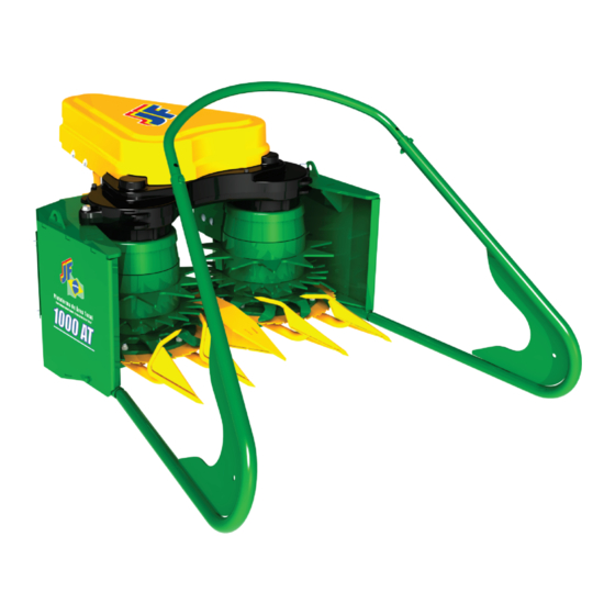
JF 1000-AT CONOCIENDO LA CABEZAL Cubierta Caja de Transmisión Chassis Tensor Alineador 10 Sierra del Tambor Dedos Alineadores 11 Eje de la Corona Tambor Tapa de la Caja Cadena... -
Page 14: Transporte Sobre Camión
Nunca permanezca bajo un equipo levantado. EMPLEO El Cabezal acoplado a una cosechadora JF (C-120, C-60, C-40, Z-10, Z-6, Z-4), cosecha con extrema precisión forrajes plantados o no en hilera, tales como maíz, sorgo, pastaje, caña, avena, etc. -
Page 15: Funcionamiento
JF 1000-AT FUNCIONAMIENTO El Cabezal de área total JF 1000-AT posee ancho de trabajo de 1 metro. Cuenta con dos tambores equipados con sistema de corte por sierras. Los tambores cosechan y recogen las plantas que son conducidas hasta los rodillos recolectores de la cosechadora, responsables por enviarlas para el rotor picador. -
Page 16: Preparación
Para acoplar el Cabezal JF 1000-AT, adquirida separadamente, en una cosechadora JF 92 Z4 / Z6 / Z10, JF C40, JF C60 o JF C-120, habrá necesidad de algunos ajustes en su cosechadora: Quitar los alineadores, el tumbador y el carenado* de la cosechadora. -
Page 17: Cambio Del Eje De La Corona De La Cosechadora
JF 1000-AT CAMBIO DEL EJE DE LA CORONA DE LA COSECHADORA Instrucciones solamente para cosechadora con caja de cambio de corte de CHAPA METALICA. Caja de chapa Caja de polietileno metálica Primero quite la tapa de protección del afilador (D). - Page 18 Manual de Instrucciones Quite los 4 tornillos (P) y desmonte el conjunto de cojinete (R). Retire el cojinete (R) de la caja. Retire los 2 pasadores (S) y desmonte el eje (T). Reemplace el eje menor (T) por el mayor (V), provisto junto con el Cabezal.
- Page 19 JF 1000-AT La figura al lado muestra el cojinete (R) con el eje mayor montado. Volver a ensamblar el cojinete (R) en la caja de la cosechadora y fijar con los 4 tornillos (P).
-
Page 20: Cambio Del Eje De La Corona De La Cosechadora
Manual de Instrucciones CAMBIO DEL EJE DE LA CORONA DE LA COSECHADORA Instrucciones solamente para cosechadora con caja de cambio de corte de POLIETILENO. Caja de chapa Caja de polietileno Primero quite la tapa de protección del afilador (D). Quite los 2 tornillos (E). Retire la tapa (F) Retire los dos engranajes de cambio del corte (G). - Page 21 JF 1000-AT Retire la caja (H) y el cerrojo (I). Quite los 4 tornillos (P). Retire el cojinete (R) de la caja. Retire los 2 pasadores (S) y desmonte el eje (T). Reemplace el eje menor (T) por el mayor (V).
- Page 22 Manual de Instrucciones La figura al lado muestra el cojinete (R) montado con el eje mayor. Monte el conjunto del cojinete (R) en la caja recolectora de la máquina. Sujete con los 4 tornillos (P). Si la cosechadora está equipada con rodillo auxiliar (T) retírela junto con los dos soportes (S).
-
Page 23: Sustitución De Los Engrasadores
JF 1000-AT SUSTITUCIÓN DE LOS ENGRASADORES Con la finalidad de facilitar la lubricación, se debe sustituir los 3 engrasadores existentes en la Cosechadora, según las instrucciones siguientes: Quitar los 3 engrasadores (A) de la cosechadora. Poner los engrasadores (B), (C) y (D) en las posiciones indicadas en la figura al lado. -
Page 24: Montaje De Las Aletas En Los Rodillos
Manual de Instrucciones MONTAJE DE LAS ALETAS EN LOS RODILLOS Montar las 6 aletas (A) provistas con el Cabezal en los rodillos de la cosechadora (son 3 en cada rodillo). Montar las aletas en los agujeros existentes en los peines de los dos rodillos. Las 6 aletas (A) son idénticas. -
Page 25: Instalación De La Tapa En El Fondo De La Caja Recolectora
JF 1000-AT INSTALACIÓN DE LA TAPA EN EL FONDO DE LA CAJA RECOLECTORA Retire la contra cuchilla inferior (F) de la plataforma. En el mismo local donde estaba la contra cuchilla (F), monte la tapa (P), cerrando el fondo de la caja (figura al lado). Utilice los mismos... -
Page 26: Instalación De Los Fijadores De La Plataforma
Manual de Instrucciones INSTALACIÓN DE LOS FIJADORES DE LA PLATAFORMA Coloque los 2 fijadores (A) en los agujeros indicados en la figura al lado. Sujete los fijadores con las tuercas (B) y arandelas (C) (figura al lado). B = Tuerca de Cabeza Hexagonal 7/16” con traba de nylon (02 un) C = Arandela Plana Ø12 x Ø29 x 4.76 (02 un) ¡NOTA! -
Page 27: Montaje De La Caja En La Cosechadora
JF 1000-AT MONTAJE DE LA CAJA EN LA COSECHADORA Monte la caja (R) en la Cosechadora nuevamente. Fije la caja en la máquina con los 3 tornillos (A) y el tornillo (B) (en ambos lados de la caja) Encaje el soporte (C) en el eje (D) y fije el mismo en la caja utilizando los 2 tornillos (E). -
Page 28: Montaje Del Deflector Central Yde Los Dedos Alineadores
Manual de Instrucciones MONTAJE DEL DEFLECTOR CENTRAL Y DEFLECTOR CENTRAL DE LOS DEDOS ALINEADORES Los dedos alineadores (derecho e izquierdo) y el deflector central (figura al lado) salen desmontados del cabezal. El montaje es simple, basta fijarlos con los tornillos, arandelas y tuercas suministradas con el cabezal. -
Page 29: Montaje De La Corona En El Cabezal
JF 1000-AT MONTAJE DE LA CORONA EN EL CABEZAL ¡NOTA! Los tornillos,tuercas y arandelas se encuentran en el kit suministrado con la plataforma. Monte el engranaje (A),fornecida con el cabezal, en el eje (B). FIJAR EL ENGRANAJE EN EL AGUJERO DE ABAJO ¡NOTA! -
Page 30: Montaje Del Tumbador En La Cabezal
Manual de Instrucciones MONTAJE DEL TUMBADOR EN LA CABEZAL Para obtener espacio y facilitar el transporte, del Cabezal por lo general se entrega con el tumbador desmontado. Para su montaje, observe las instrucciones a continuación. Encaje los dos tumbadores (A) en el Cabezal (B). -
Page 31: Montaje De La Cabezal En La Cosechadora
JF 1000-AT MONTAJE DE LA CABEZAL EN LA COSECHADORA Monte el Cabezal en la cosechadora, encajando en los dos fijadores (L). Fije el Cabezal en la cosechadora con los 2 tornillos y arandelas (M). M = Tornillo cabeza hexagonal 7/16” x 2” (02 un) M = Arandela plana Ø43 mm x Ø12 mm x 6,35... -
Page 32: Montaje De La Corona En Ela Cosechadora
Manual de Instrucciones MONTAJE DE LA CORONA EN ELA COSECHADORA Observe que junto con el cabezal se suministran algunos espaciadores (A). Estos espacioadores se utilizan para alinear la corona (B) con la corona del cabezal (C). Coloque la corona (B) en el eje, utilizando 3 espaciadores debajo de la corona. -
Page 33: Montaje Del Tensor De La Cadena
JF 1000-AT TENSOR MONTAJE DEL TENSOR DE LA CADENA Coloque el tensor en los dos pines del cabezal, como se muestra en la ilustración al lado. Utilice 2 espaciadores (D) en cada pin. ESPACIADOR (D) 26 mm 1,9 mm REGLA 16,5 mm Después del acoplamiento, utilice una regla y... -
Page 34: Colocación De La Cadena
K = Arandela plana 3/8” (04 un) Por último, coloque la tapa protectora del afilador (T). Fijarla con la tuerca y arandela plana. La figura al lado muestra el Cabezal JF 1000-AT montada en la cosechadora ¡NOTA! Los tornillos,tuercas y arandelas se encuentran... -
Page 35: Engrase
JF 1000-AT ENGRASE El engrase adecuado y regular es indispensable para el buen desempeño y durabilidad de la máquina. Los intervalos indicados llevan en consideración su utilización en condiciones normales de trabajo. En condiciones severas, deben ser reducidos. Se recomienda las inspecciones periódicas y la utilización de lubricantes limpios y de buena... -
Page 36: Lubricación De La Cadena (D)
Manual de Instrucciones LUBRICACIÓN DE LA CADENA (D) La lubricación adecuada prolonga la vida útil, evita la oxidación y el desgaste prematuro de las cadenas. Aplique una fina camada de aceite especial para cadenas, como el MAXLUB ND-03 Bardahl. Si disponible, utilice lubricante especial para cadenas (grasa en spray), pues ella proporciona una lubricación más eficiente entre los pasadores y rodillos de las cadenas. -
Page 37: Conservación
JF 1000-AT CONSERVACIÓN Se recomienda realizar preferencialmente al final de cada temporada, una revisión general en la máquina, identificando y reemplazando partes con desgaste o dañadas. Recuerde que el período entre temporadas es el mejor momento para realizar el mantenimiento preventivo y así permanecer tranquilo para la próxima cosecha. -
Page 38: Características Técnicas
Manual de Instrucciones CARACTERÍSTICAS TÉCNICAS Potencia exigida en la 60 a 80 cv toma de fuerza Rotación en la toma de 540 rpm fuerza Peso líquido (Kg) Espaciamiento de trabajo 1 metro Producción hasta 35 ton/ hora ƒ La productividad puede variar y depende del los siguientes factores: tamaño de picado;... -
Page 39: Tabla De Torque Para Tornillo Rosca Métrica
JF 1000-AT TABLA DE TORQUE PARA TORNILLO ROSCA MÉTRICA Unidad de torque: N.m... -
Page 40: Tabla De Torque Para Tornillo Rosca Pulgada
Manual de Instrucciones TABLA DE TORQUE PARA TORNILLO ROSCA PULGADA Unidad de torque: N.m... -
Page 41: Tabla De Medida De Llaves
JF 1000-AT TABLA DE MEDIDA DE LLAVES... - Page 42 Manual de Instrucciones...
-
Page 43: Término De Garantía
JF 1000-AT Término de Garantía El equipo agrícola descrito en este manual es garantizado por JF Máquinas Agrícolas LTDA. por un período de 01 (un) año a partir de la fecha de emisión de la factura de venta al primer propietario/consumidor de este producto, confirmado a través del Comprobante de Entrega Técnica. - Page 44 Manual de Instrucciones...
- Page 45 JF 1000-AT...
- Page 46 Manual de Instrucciones En el caso de que el revendedor no haya efectuado la Entrega Técnica, llenar apenas la parte superior. Tras el llenado (parcial o total), el cliente debe quedarse con esta vía En el caso de que el revendedor no haya efectuado la Entrega Técnica, llenar apenas la parte superior.
- Page 47 JF 1000-AT Mr. Owner Congratulations on your purchase of the JF 1000-AT Row Independent Head, a product of the highest quality, specially developed to meet your needs. This manual contains operating, maintenance and safety instructions, which, if properly observed, will guarantee the proper functioning and durability of your Head.
- Page 48 Operation Technical Manual INDEX Index ..............................4 Identification ............................5 Environment ............................5 Safety precautions ..........................6 General safety ............................. 6 Safety in preparation ........................... 7 Operational safety ..........................8 Safety in maintenance ......................... 9 Transport safety ..........................10 Seguridad personal ........................... 10 Clearance opening ..........................11 Safety stickers ...........................
- Page 49 JF 1000-AT IDENTIFICATION Your Head is identified with a serial number, located on the plate fixed on the machine body. Enter the serial number of your machine here: IMPORTANT! When sending communications or requesting service assistance, always state the machine serial number and model number on the nameplate.
- Page 50 Operation Technical Manual CAUTION! SAFETY PRECAUTIONS The operator must be familiar with The word “CAUTION” indicates situations where the operating and maintenance there is potential hidden risk, the consequences procedures and the SAFETY of which, if not avoided, can lead to serious injury. information contained in this manual.
- Page 51 JF 1000-AT static, without turning. Never use cardans without SAFETY IN PREPARATION safety protection. ƒ Make sure that the machine is correctly engaged to the tractor and the locking pin properly locked. ƒ Before starting the operation, perform a general check on the...
- Page 52 Operation Technical Manual ƒ Do not allow children or bystanders to approach OPERATIONAL SAFETY the machine when operating or during maneuvers. ƒ Do not operate the machine ƒ Keep all shields and guards in place and do not if you have ingested alcoholic operate the machine without them.
- Page 53 JF 1000-AT SAFETY IN MAINTENANCE it is motionless. Always be attentive! ƒ HYDRAULIC SYSTEM ƒ Disconnect the power take-off, ƒ If it is necessary to work on the machine the tractor engine and remove suspended by the hydraulic, it must be supported the ignition key before adjusting, in a safe way.
- Page 54 Operation Technical Manual TRANSPORT SAFETY SEGURIDAD PERSONAL ƒ The safety of the operator and others is ƒ The transport of the machine coupled to the tractor must not ƒ a major concern in the design and development be carried out on public roads and of a machine.
- Page 55 RIGHT We remind you that the harvester coupled with a USE A JF CHOPPER ALWAYS WHAT JF 1000-AT Head has not been developed and is YOU NEED TO FEED WITH YOUR not suitable for manual feeding since this procedure HANDS.
- Page 56 Operation Technical Manual SAFETY STICKERS Do not open or remove covers and safety guards while the machine is running. Keep your hands away from the chain and other moving parts that could catch them, causing personal injury. Keep distance and do not allow people near the feeder drum while the machine is on.
- Page 57 JF 1000-AT KNOWING THE HEAD Cover Transmission gearbox Chassis Stretcher Aligner 10 Drum Saw Aligner fingers 11 Crown shaft Drum Harvester Box Cover Chain...
- Page 58 Never stand under suspended equipment. USAGE The head coupled to a JF harvester (C-120, C-60, C-40, Z-10, Z-6, Z-4) harvests with extreme accuracy forage crops planted in line or not, such as corn, sorghum, grasses, cane, oats, etc.
- Page 59 JF 1000-AT OPERATION The JF 1000-AT row independent head has a working aperture of 1 meter. It has two drums equipped with cutting system by saws. The drums harvest and collect the plants which are led to the feeding drums of the harvester, responsible for the routing to the chopping rotor.
- Page 60 Operation Technical Manual PREPARATION To fit the separately purchased JF 1000-AT in a JF 92 Z4 / Z6 / Z10, JF C40, JF C60 or JF C-120 harvester, some adjustments will be required on your harvester: ƒ Remove the aligners, bender and fairing* from the harvester.
- Page 61 JF 1000-AT REPLACING AXLE OF THE HARVEST CROWN Instructions only for harvester with cutter gearbox of SHEET METAL. Sheet metal Polyethylene gearbox gearbox First remove the protective cap from the grinder (D). Remove the two bolts (E). Remove the cap (F).
- Page 62 Operation Technical Manual Remove the 4 bolts (P) and remove the bearing assembly (R). Remove the bearing (R) of the box. Remove the two pins (S) and remove the shaft (T). Replace the minor shaft (T) by the major shaft (V) supplied with the platform.
- Page 63 JF 1000-AT The figure on the side shows the bearing (R) with the major shaft mounted. Refit the bearing (R) on the harvester platform and secure them with the 4 bolts (P).
- Page 64 Operation Technical Manual HARVESTER CROWN AXLE REPLACEMENT Instructions only for harvester with cutting change box of POLYETHYLENE Sheet metal Polyethylene gearbox gearbox First remove the protective cap from the grinder (D). Remove the 2 bolts (E). Remove the cap (F). Remove the two cutting change gears (G).
- Page 65 JF 1000-AT Remove the box (H) and the handcuff (I). Remove the 4 bolts (P). Remove the bearing (R) of the platform. Remove the two pins (S) and remove the shaft (T). Replace the minor shaft (T) by the major...
- Page 66 Operation Technical Manual The figure on the side shows the bearing (R) with the major shaft mounted. Assemble the bearing assembly (R) in the machine gathering platform. Secure with the 4 bolts (P) If the harvester is equipped with auxiliary roller (T), remove it together with the two supports (S)..
- Page 67 JF 1000-AT REPLACEMENT GREASE FITTINGS In order to facilitate lubrication, it is necessary to replace the 3 grease existing in the Harvester, as follows: Remove the three grease fittings (A) from the harvester. Place the grease fittings (B), (C) and (D) following the picture besides.
- Page 68 Operation Technical Manual ASSEMBLY THE VANES ON THE FEEDING DRUMS Assemble the 6 vanes (A) provided with the head on the feeding drums of the harvester (they are 3 on each roll). Fit the vanes into the holes in the combs of the two feeding drums..
- Page 69 JF 1000-AT INSTALLING THE COVER ON THE BOTTOM OF THE GATHERING PLATFORM Remove the lower counter-knife (F) from the platform. In the same place as the counter-knife (F), fit the cover (P), closing the bottom of the platform (figure on the side).
- Page 70 Operation Technical Manual INSTALLING THE HEAD FASTENERS Insert the two fasteners (A) into the holes indicated in the figure on the side. Secure the fasteners with the nuts (B) and washers (C) (figure on the side). B = hex nut 7/16” with nylon lock (02 un) C = flat washer Ø12 x Ø29 x 4.76 (02 un) NOTE! The screws, nuts and washers are located in the...
- Page 71 JF 1000-AT ASSEMBLY THE PLATFORM IN THE HARVESTER Assemble the platform in the Harvester again. Attach the platform to the machine with the 3 bolts (A) and the bolt (B) (on both sides of the platform). Insert the support (C) to the shaft (D) and attach it to the platform using the 2 bolts (E).
- Page 72 Operation Technical Manual ASSEMBLY OF THE CENTRAL CENTRAL DEFLECTOR DEFLECTOR AND THE ALIGNER FINGERS The aligner fingers (right and left) and the central deflector (figure on the side) goes disassembled from the head. Their assembly is easy, just fix them with bolts, washers and nuts supplied with the head.
- Page 73 JF 1000-AT ASSEMBLY OF THE SPROCKET ON THE HEAD Put the sprocket (A) on the shaft (B). Fix the sprocket (A) on the shaft with the hex bolt (D), flat washer (C) and hex nut (E). FIX THE SPROCKET I N T H E B O T T O M...
- Page 74 Operation Technical Manual ASSEMBLY THE BENDER IN THE HEAD To gain space and facilitate transportation, the head is usually provided with the bender removed. For assembly, follow the instructions below. Fit the two aligners (A) on the head.(B). Fit the bender (C) on the aligners. Fix both aligners (A) with bolts (E) and nuts (F) on both sides of the head.
- Page 75 JF 1000-AT ASSEMBLY THE HEAD IN THE HARVESTER Assemble the head in the harvester, fitting it to the two fasteners (L). Attach the platform to the machine with the 2 bolts and washers (M). M = hex nut 7/16” with nylon lock (02 un) M = flat washer Ø12 x Ø29 x 4.76 (02 un)
- Page 76 Operation Technical Manual ASSEMBLY OF THE SPROCKET ON THE HARVESTER Observe that with the head, some spacers (A) are supplied. These spacers are used for aligning the sprocket (B) with the head’s sprocket (C). Put the sprocket (B) on the shaft, using three spacers under the sprocket.
- Page 77 JF 1000-AT TENSIONER ASSEMBLY OF THE CHAIN TENSIONER Fit the chain tensioner on the two pins of the head, as shown in the picture besides. Use two shims (D) in each pin. SHIM (D) 26 mm 1,9 mm RULER 16,5 mm...
- Page 78 J = Hex bolt 5/16” X 3/4” (04 un) K = Flat washer 3/8” (04 un) Finally, assemble the sharpener cover of the harvester (T) The picture besides shows the Head JF 1000 AT assembled in the harvester. NOTE! The screws, nuts and washers are located in the...
- Page 79 JF 1000-AT GREASING Proper and regular lubrication is indispensable for the good performance and durability of the machine. The indicated intervals take into account their use under normal working conditions. Under severe conditions, they should be reduced. Periodic inspections and the use of clean, good quality lubricants are recommended.
- Page 80 Operation Technical Manual LUBRICATION OF THE CHAIN Proper lubrication prolongs the service life, prevents oxidation and premature wear of the chains. Apply a light coat of special oil for chains, such as the MAXLUB ND-03 Bardahl. If available, use special chain lubricant (spray grease) as it provides more efficient lubrication between the chain pins and rollers.
- Page 81 JF 1000-AT CONSERVATION It is recommended to carry out a general overhaul of the machine, preferably at the end of each season, by identifying and replacing worn or damaged parts. Remember that the off-season is the best time to do preventive maintenance and so be quiet for the next harvest.
- Page 82 Operation Technical Manual TECHNICAL SPECIFICATIONS Required Power 60 a 80 cv inn the power take-off PTO speed 540 rpm Net weight (Kg) Working spacing 1000 mm Yield up to 35 ton/h ƒ Productivity mightvary and depends on lhe following factors: cut size; productivity of forage per hectare; tractor power;...
- Page 83 JF 1000-AT TORQUE CHART FOR METRIC THREAD SCREW Torque unit: N.m...
- Page 84 Operation Technical Manual TORQUE CHART FOR INCH THREAD SCREW Torque unit: N.m...
- Page 85 JF 1000-AT KEY GAUGE TABLE...
- Page 86 Operation Technical Manual...
- Page 87 JF 1000-AT Warranty Term The agricultural equipment described in this manual is guaranteed by JF Máquinas Agrícolas LTDA. for a period of 01 (one) year from the date of issuance of the sales tax bill to the first owner / consumer of this product, confirmed by the Proof of Technical Delivery.
- Page 88 Operation Technical Manual...
- Page 89 JF 1000-AT...
- Page 90 Operation Technical Manual If the reseller has not delivered the Technical Delivery, fill in only the head After filling in (partial or total), the customer must follow this via. If the reseller has not delivered the Technical Delivery, fill in only the head. After filling in (partial or total), the customer must follow this via.
- Page 92 LA SOLUCIÓN PARA EL PRODUCTOR THE SOLUTION FOR THE PRODUCER JF Máquinas Agrícolas Ltda. CNPJ: 46.127.635/0001-55 Rua Santa Terezinha, Nº921. Dirección............. Jd. Guarujá - Itapira - SP - Brasil CP: 13973-900 Caja Postal: 114. (+55 19) 3863-9642 Departamento de Posventa.........
Need help?
Do you have a question about the 1000 AT and is the answer not in the manual?
Questions and answers