Table of Contents
Advertisement
Available languages
Available languages
Quick Links
Introduction
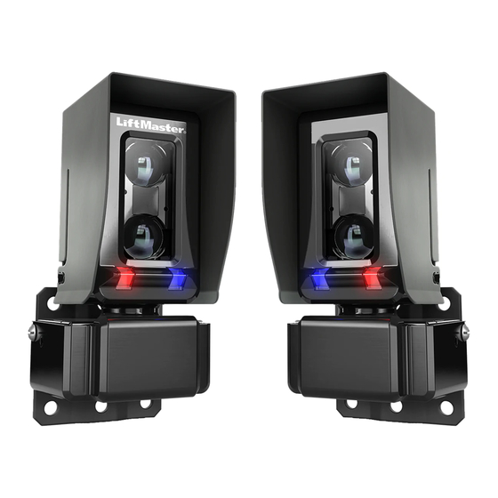
The LiftMaster
®
Photoelectric Sensors provide
non-contact monitored entrapment protection. For
use with LiftMaster
®
UL Listed gate operators. The
sensors are UL recognized components and meet UL
325 requirements. Monitored external entrapment
protection devices MUST be installed at each
Entrapment Zone. Refer to gate operator manual for
compatibility with LMTBUL sensor.
Specifi cations
Max Range: 90 ft. (27.4 m)
Sensor Dimensions with Hood: 2.29" W x 3.72" H x
2.76" D
Cable Length: 10 ft. (3 m)
Operating Temperature: -40˚C to 65˚C (-40˚F to
149˚F)
Outdoor Rating: Nema 4X
Heater: Thermostatically controlled, NOT
recommended for solar applications
To prevent possible SERIOUS INJURY or DEATH from a closing gate or door:
•
Read and follow ALL instructions.
•
Be sure to DISCONNECT ALL POWER to the operator BEFORE installing the photoelectric sensors.
•
The gate or door MUST be in the fully opened or closed position BEFORE installing the LiftMaster
Monitored Entrapment Protection device.
•
Correctly connect and align the photoelectric sensor.
•
Install the photoelectric sensor so that the center of the sensor window is NO HIGHER than 4-1/2"
(11.4 cm) above the fl oor for door operators and 26" (66 cm) above grade for gate operators.
•
Monitored external entrapment protection devices MUST be installed per the operator installation
manual at each Entrapment Zone.
•
The sensors MUST be mounted vertically.
•
Test the gate operator and ALL photoelectric sensors monthly. Replace ANY damaged devices.
•
SAVE THESE INSTRUCTIONS.
WARNING: This product can expose you to chemicals including lead, which are known
to the State of California to cause cancer or birth defects or other reproductive harm.
For more information go to www.P65Warnings.ca.gov.
MONITORED THROUGH BEAM
PHOTOELECTRIC SENSOR
Input Voltage:
Sensor: Black/red wires 6.8 VDC, 20mA
Heater: Green/white wires 10-40VDC or 8-28 VAC,
4 watts max., 170mA per pair @ 24 VDC/VAC,
340mA per pair @ 12 VDC/VAC
Model LMTBUL
®
Advertisement
Table of Contents

Related Manuals for Chamberlain LMTBUL


Summary of Contents for Chamberlain LMTBUL
- Page 1 325 requirements. Monitored external entrapment protection devices MUST be installed at each Entrapment Zone. Refer to gate operator manual for compatibility with LMTBUL sensor. Specifi cations Max Range: 90 ft. (27.4 m) Sensor Dimensions with Hood: 2.29" W x 3.72" H x 2.76"...
-
Page 2: Carton Inventory
Carton Inventory Tools Needed • Emitter with hood and bracket • Thread-locking screws • Philips screwdriver • Receiver with hood and 10-32x1" (4) • 7/16" socket bracket • M3 screw (2) • Wire covers (2) • Set screw 10-32x3/8" (2) •... - Page 3 Wiring Sensor wiring (red and black wires): Wire the photoelectric sensors (red [+] and black [-] wires) to the appropriate inputs on the operator or expansion board as shown. Heater wiring (green and white wires): • OPTION 1 - Connect to the ACCESSORY POWER ON terminal on the control board (NOT polarity specifi c). •...
- Page 4 Alignment Reconnect power to the operator. Align the sensors. The LEDs on the RECEIVER indicate alignment. The red LED indicates misalignment or blocked sensor. The blue LED indicates signal strength. Slow blinking indicates weak signal. Fast blinking indicates stronger signal. Solid blue LED on the receiver indicates optimal alignment. NOTE: Solid blue LED on the EMITTER indicates the sensor is powered.
-
Page 5: Troubleshooting
Troubleshooting Symptom Possible Cause Solution Gate does not move 1. Minimum number of 1. Review sensor connections. Slide gate operators require entrapment protection a minimum of two external monitored devices; one in the devices not installed close and one in the open direction. 2. -
Page 6: Caractéristiques Techniques
UL 325. Des dispositifs surveillés de protection contre le piégeage DOIVENT être installés dans chaque zone de piégeage. Consulter le manuel de l’actionneur de barrière pour la compatibilité avec le capteur LMTBUL. Caractéristiques techniques Portée maximale : 27,4 m (90 pi) Chauffage : Régulé par thermostat, NON Dimensions du capteur avec le capot : 5,81 cm... -
Page 7: Outils Nécessaires
Inventaire de la boîte Outils nécessaires • Émetteur avec capot et support • Vis à frein-fi let 10-32x1 po (4) • Tournevis à tête cruciforme • Réfl ecteur avec capot et • Vis M3 (2) • Douille de 7/16 po support •... - Page 8 Câblage Câblage du capteur (fi ls rouge et noir) : Câbler les capteurs à cellule photoélectrique (fi ls rouge [+] et noir [-]) aux entrées appropriées sur l’actionneur ou la carte d’extension, comme montré. Câblage de l’appareil de chauffage (fi ls vert et blanc) : •...
- Page 9 Alignement Remettre l’alimentation à l’actionneur. Aligner les capteurs. Les DEL sur le RÉCEPTEUR indiquent l’alignement. La DEL rouge indique un capteur désaligné ou obstrué. La DEL bleue indique la puissance du signal. Un clignotement lent indique un signal faible. Un clignotement rapide indique un signal plus fort. La DEL bleue allumée en continu indique un alignement optimal.
-
Page 10: Dépannage
Dépannage Symptôme Cause possible Solution La barrière ne bouge pas. 1. Nombre minimal de 1. Examiner les connexions du capteur. Les dispositifs de protection actionneurs de barrière coulissante exigent au contre le piégeage non minimum deux dispositifs externes surveillés, un installés. -
Page 11: Especificaciones
DEBEN instalarse dispositivos de protección contra atrapamiento monitoreados externos. Consulte el manual del operador de portón para ver la compatibilidad con el sensor LMTBUL. Especifi caciones Rango máximo: 27.4 m (90 pies) Dimensiones del sensor con la campana: 5.81 cm (2.29 pulg.) Ancho x 9.45 cm (3.72 pulg.) Alto x... -
Page 12: Contenido De La Caja
Contenido de la caja Herramientas necesarias • Emisor con campana y • Tuercas de seguridad de ménsula 1/4 pulg.-20 (4) • Destornillador estrella • Receptor con campana y • Tornillo de bloqueo roscado • Llave de tubo de 7/16 ménsula 10-32x1 pulg. (4) •... - Page 13 Cableado Cableado del sensor (cables rojo y negro): Conecte los sensores fotoeléctricos (cables rojo [+] y negro [-]) a las entradas adecuadas en el operador o el tablero de expansión tal como se muestra. Cableado del calentador (cables verde y blanco): •...
- Page 14 Alineación Vuelva a conectar la alimentación eléctrica al operador. Alinee los sensores. Los DEL en el RECEPTOR indican la alineación. El DEL rojo indica un sensor desalineado o bloqueado. El DEL azul indica la potencia de la señal. El parpadeo lento indica una señal débil.
-
Page 15: Resolución De Problemas
Resolución de problemas Síntoma Posible causa Solución El portón no se mueve 1. No se ha instalado el número 1. Revise las conexiones del sensor. Los operadores mínimo de dispositivos de de portón deslizante requieren como mínimo dos monitoreo de protección dispositivos de monitoreo externo;... - Page 16 © 2018, LiftMaster All Rights Reserved Tous droits réservés 01-39359B Todos los Derechos Reservados LiftMaster.com...
Need help?
Do you have a question about the LMTBUL and is the answer not in the manual?
Questions and answers