Table of Contents
Advertisement
Quick Links
M1.2.HB240-HB240M.NLFREN 21112017
P.02 Gelieve te lezen en voor later gebruik bewaren
NL
P.16 Veuillez lire et conserver pour consultation ultérieure
FR
P.30 Please read and keep for future reference
EN
HANDLEIDING - MODE D'EMPLOI - MANUAL
HB240 (724563060)
HB240M (724563058)
Twee koloms hefbrug
Pont à colonne double
Two post lift
Advertisement
Chapters
Table of Contents

Subscribe to Our Youtube Channel
Related Manuals for MW TOOLS HB240


Summary of Contents for MW TOOLS HB240
- Page 1 M1.2.HB240-HB240M.NLFREN 21112017 HANDLEIDING - MODE D’EMPLOI - MANUAL HB240 (724563060) HB240M (724563058) Twee koloms hefbrug Pont à colonne double Two post lift P.02 Gelieve te lezen en voor later gebruik bewaren P.16 Veuillez lire et conserver pour consultation ultérieure P.30 Please read and keep for future reference...
-
Page 2: Table Of Contents
M1.2.HB240-HB240M.NLFREN 21112017 Inhoud 1 Belangrijke veiligheidsvoorschriften ���������������������������������������������������������������������������������������������������3 1.1 Belangrijke opmerkingen ............................3 1.2 Kwalificatie van het personeel ..........................3 1.3 Waarschuwingen ..............................3 1.4 Waarschuwingsbordje ............................3 2 Overzicht van de machine ������������������������������������������������������������������������������������������������������������������5 2.1 Algemene omschrijving ............................5 2.2 Technische gegevens ............................5 2.3 De brug assembleren ............................ -
Page 3: Belangrijke Veiligheidsvoorschriften
M1.2.HB240-HB240M.NLFREN 21112017 1 Belangrijke veiligheidsvoorschriften 1�1 Belangrijke opmerkingen Tijdens de garantieperiode, wordt elk kwalitatief probleem worden opgelost ten genoegen van de klant. We aanvaarden echter geen aansprakelijkheid in geval van problemen als gevolg van onjuiste installatie, niet toepasselijk gebruik van de machine, overbelasting of installatie op een ongeschikte grond. - Page 4 USER’S GUIDE V1.0 201511 M1.2.HB240-HB240M.NLFREN 21112017 1.5 Warning signs USER’S GUIDE V1.2 201503 USER’S GUIDE V1.2 201503 1.5 Warning signs 1.5 Warning signs 1.5 Warning signs 1.5 Warning signs All safety warning signs attached on the machine are for the purpose of drawing the user’s attention to safety operation. The...
-
Page 5: Overzicht Van De Machine
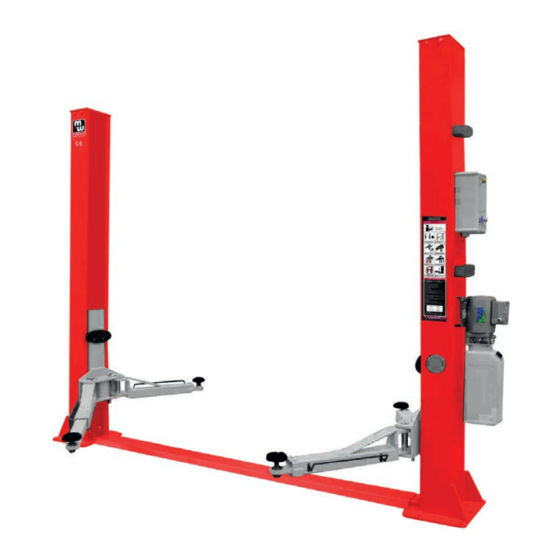
M1.2.HB240-HB240M.NLFREN 21112017 2 Overzicht van de machine USER’S GUIDE V1.0 201511 OVERVIEW OF THE LIFT 2�1 Algemene omschrijving 2.1 General descriptions Deze hefbrug bestaat uit twee kolommen die onderaan met een plaat worden gekoppeld, een drager, twee hefarmen, cilinders en een motor, enz. -
Page 6: De Brug Assembleren
M1.2.HB240-HB240M.NLFREN 21112017 2.2 Technical data Model Lifting capacity Full rise time Full rise Height Width Inside columns Two post lift 4000kg 1930mm 2824mm 3365mm 2780mm 2�3 De brug assembleren 2.3 Construction of the lift Bovenplaat Oliecilinder Kolom Drager Hefarm Voedingseenheid... -
Page 7: Vereisten Voor De Installatie
3.2 Precautions for installation M1.2.HB240-HB240M.NLFREN 21112017 3.2.1 Make sure the two posts stand paralleled and are vertical to the ground. No slanting. 3.2.2 Joints of oil hose and steel cable must be firmly connected in order to avoid the looseness of steel cable and leakage of oil hose. - Page 8 USER’S GUIDE V1.0 201511 M1.2.HB240-HB240M.NLFREN 21112017 Step6: Connect steel cables. Route and fix according to the following diagram of steel cable connection. 6� Sluit de staalkabels aan (fig. 7). Raise carriages on both sides approximately 800mm above the ground. Carriages must be on the same height from the floor.
- Page 9 M1.2.HB240-HB240M.NLFREN 21112017 7� Monteer voedingseenheid op de kolom (fig. 8). 8� Sluit de olieslangen aan volgens het schema (fig. 9). Fig 7 Step7: Mount the power unit onto the power side post. (Fig 8) Hex M8 bout M8 sluitring Hex M8*16 bout Step8: Connect oil hoses.
- Page 10 M1.2.HB240-HB240M.NLFREN 21112017 USER’S GUIDE V1.0 201511 9� Sluit de kabels aan (fig. 10). Step9: Connect wires. 1. Monteer de bedieningskast op de kolom met de voedingseenheid. 1. Mount the control box on to the power side post. USER’S GUIDE V1.0 201511...
- Page 11 USER’S GUIDE V1.0 201511 M1.2.HB240-HB240M.NLFREN 21112017 Step10: Install lifting arms. USER’S GUIDE V1.0 201511 Connect the lifting arm and the carriage by shafts. Step10: Install lifting arms. Install the lifting arms onto the carriages and ensure the arm lock could work.
-
Page 12: Punten Te Controleren Na De Installatie
3.4 Items to be checked after installation. M1.2.HB240-HB240M.NLFREN 21112017 Check items Are the posts vertical to the floor? Are the two posts paralleled? Is the oil hose well connected? 3�4 Punten te controleren na de installatie Is the steel cable well connected? -
Page 13: De Hefbrug Laten Stijgen En Dalen
M1.2.HB240-HB240M.NLFREN 21112017 USER’S GUIDE V1.0 201511 4�3 De hefbrug laten stijgen en dalen 4.3 Operation instructions Knop UP Ontgrendeling staalkabel Ontladingshendel Fig� 15 Raise the lift 4�3�1 Een voertuig heffen Make sure that you have read and understood the operation manual before operation. -
Page 14: Problemen Oplossen
M1.2.HB240-HB240M.NLFREN 21112017 5 Problemen oplossen AANDACHT! Indien u een probleem met behulp van onderstaande tabel niet kunt oplossen, aarzel niet de technische dienst van uw verdeler te contacteren, we helpen u zo snel mogelijk� Voor een betere dienst, stuur ons alstublieft een gedetailleerde omschrijving van het defect, en eventueel een foto�... -
Page 15: Onderhoud
M1.2.HB240-HB240M.NLFREN 21112017 USER’S GUIDE V1.0 201511 6 Onderhoud MAINTENANCE Een regelmatig onderhoud, eenvoudig en niet duur, garandeert een normale en veilige werking van uw machine. De volgende aanwijzingen zijn voor routineonderhoud. De frequentie van onderhoudwerkzaamheden wordt bepaald door de w cost routine maintenance can ensure the lift work normally and safely. Following are requirements for routine werkomstandigheden. - Page 16 M1.2.HB240-HB240M.NLFREN 21112017 Table des matières 1 Consignes de sécurité importantes ��������������������������������������������������������������������������������������������������� 17 1.1 Remarques importantes ............................17 1.2 Qualification du personnel ..........................17 1.3 Avertissements ..............................17 1.4 Panneaux d’avertissements ..........................17 2 Présentation de la machine �������������������������������������������������������������������������������������������������������������� 19 2.1 Description générale ............................19 2.2 Données techniques ............................
-
Page 17: Consignes De Sécurité Importantes
M1.2.HB240-HB240M.NLFREN 21112017 1 Consignes de sécurité importantes 1�1 Remarques importantes Pendant la période de garantie, tout problème qualitatif sera résolu à la satisfaction du client. Toutefois, nous déclinons toute responsabilité en cas de problème dû à une installation ou une utilisation incorrecte de la machine, une surcharge ou une installation de la machine sur un sol non adapté. - Page 18 USER’S GUIDE V1.0 201511 M1.2.HB240-HB240M.NLFREN 21112017 1.5 Warning signs All safety warning signs attached on the machine are for the purpose of drawing the user’s attention to safety operation. The labels must be kept clean and need to be replaced when they are worn-out or have dropped. Read the explanations of the labels carefully and try to memorize them.
-
Page 19: Présentation De La Machine
M1.2.HB240-HB240M.NLFREN 21112017 2 Présentation de la machine USER’S GUIDE V1.0 201511 OVERVIEW OF THE LIFT 2�1 Description générale 2.1 General descriptions Ce pont est composé de deux colonnes reliées entre elles par une plaque, d’un chariot, de deux bras de levage, de cylindres et This floor plate two posts lift is composed of posts, carriages, lifting arms, cylinders and motor unit, etc. -
Page 20: Assemblage Du Pont
M1.2.HB240-HB240M.NLFREN 21112017 2.2 Technical data Model Lifting capacity Full rise time Full rise Height Width Inside columns Two post lift 4000kg 1930mm 2824mm 3365mm 2780mm 2�3 Assemblage du pont 2.3 Construction of the lift Plaque supérieure Cylindre d’huile Colonne Chariot Bras de levage Bloc d’alimentation... -
Page 21: Exigences Pour L'installation
3.2 Precautions for installation M1.2.HB240-HB240M.NLFREN 21112017 3.2.1 Make sure the two posts stand paralleled and are vertical to the ground. No slanting. 3.2.2 Joints of oil hose and steel cable must be firmly connected in order to avoid the looseness of steel cable and leakage of oil hose. - Page 22 M1.2.HB240-HB240M.NLFREN 21112017 USER’S GUIDE V1.0 201511 Step6: Connect steel cables. Route and fix according to the following diagram of steel cable connection. 6� Connectez les câbles en acier (fig. 7). Raise carriages on both sides approximately 800mm above the ground. Carriages must be on the same height from the floor.
- Page 23 M1.2.HB240-HB240M.NLFREN 21112017 7� Montez le groupe moteur sur la colonne (fig. 8). Fig 7 8� Branchez les tuyaux d’huile suivant le schéma (fig. 9). Step7: Mount the power unit onto the power side post. (Fig 8) Boulon hex M8 Rondelle M8 Boulon hex M8*16 Step8: Connect oil hoses.
- Page 24 M1.2.HB240-HB240M.NLFREN 21112017 USER’S GUIDE V1.0 201511 9� Branchez les câbles (fig. 10). 1. Montez le boîtier de commande sur la colonne avec le bloc d’alimentation. Step9: Connect wires. 1. Mount the control box on to the power side post. USER’S GUIDE V1.0 201511 Boîtier de commande...
- Page 25 USER’S GUIDE V1.0 201511 M1.2.HB240-HB240M.NLFREN 21112017 USER’S GUIDE V1.0 201511 Step10: Install lifting arms. Connect the lifting arm and the carriage by shafts. Step10: Install lifting arms. Install the lifting arms onto the carriages and ensure the arm lock could work.
-
Page 26: Points À Contrôler Après L'installation
3.4 Items to be checked after installation. M1.2.HB240-HB240M.NLFREN 21112017 Check items Are the posts vertical to the floor? Are the two posts paralleled? Is the oil hose well connected? 3�4 Points à contrôler après l’installation Is the steel cable well connected? Are all lifting arms well fixed? Points à... -
Page 27: Lever Et Abaisser Le Pont
M1.2.HB240-HB240M.NLFREN 21112017 USER’S GUIDE V1.0 201511 4�3 Lever et abaisser le pont 4.3 Operation instructions Bouton UP Câble de déverrouillage Levier de déchargement Fig� 15 Raise the lift Make sure that you have read and understood the operation manual before operation. -
Page 28: Résolution Des Problèmes
M1.2.HB240-HB240M.NLFREN 21112017 5 Résolution des problèmes ATTENTION ! Si vous ne pouvez pas résoudre un problème avec le tableau ci-dessous, n’hésitez pas à contacter le service technique de votre revendeur� Nous vous aiderons dans les meilleurs délais� Pour un meilleur service, veuillez envoyer une description détaillée de la panne et éventuellement une photo�... -
Page 29: Entretien
M1.2.HB240-HB240M.NLFREN 21112017 USER’S GUIDE V1.0 201511 6 Entretien MAINTENANCE Un entretien régulier, facile et peu coûteux, assure un fonctionnement correct et sûr de votre machine. Les explications qui suivent concernent l’entretien de routine. La fréquence des entretiens est déterminée par les conditions de travail. - Page 30 M1.2.HB240-HB240M.NLFREN 21112017 Contents 1 Important safety instructions ������������������������������������������������������������������������������������������������������������31 1.1 Important notices ...............................31 1.2 Qualified personnel ............................31 1.3 Danger notices ..............................31 1.4 Warning signs ..............................31 2 Overview of the lift ��������������������������������������������������������������������������������������������������������������������������33 2.1 General description ............................33 2.2 Technical data ..............................33 2.3 Construction of the lift ............................34 3 Installation instructions ��������������������������������������������������������������������������������������������������������������������34...
-
Page 31: Important Safety Instructions
M1.2.HB240-HB240M.NLFREN 21112017 1 Important safety instructions 1�1 Important notices During the warranty period, any quality problem will be properly solved to the user’s satisfaction. However, we will not take any responsibility for whatever bad consequence resulted from improper installation and operation, overload running or unqualified ground condition. - Page 32 USER’S GUIDE V1.0 201511 M1.2.HB240-HB240M.NLFREN 21112017 1.5 Warning signs All safety warning signs attached on the machine are for the purpose of drawing the user’s attention to safety operation. The labels must be kept clean and need to be replaced when they are worn-out or have dropped. Read the explanations of the labels carefully and try to memorize them.
-
Page 33: Overview Of The Lift
M1.2.HB240-HB240M.NLFREN 21112017 USER’S GUIDE V1.0 201511 2 Overview of the lift OVERVIEW OF THE LIFT 2�1 General description 2.1 General descriptions This floor plate two posts lift is composed of posts, carriages, lifting arms, cylinders and motor unit, etc. This floor plate two posts lift is composed of posts, carriages, lifting arms, cylinders and motor unit, etc. -
Page 34: Construction Of The Lift
M1.2.HB240-HB240M.NLFREN 21112017 2.2 Technical data Model Lifting capacity Full rise time Full rise Height Width Inside columns Two post lift 4000kg 1930mm 2824mm 3365mm 2780mm 2�3 Construction of the lift 2.3 Construction of the lift Fig� 2 Construction of the lift... -
Page 35: Precautions For Installation
3.2 Precautions for installation M1.2.HB240-HB240M.NLFREN 21112017 3.2.1 Make sure the two posts stand paralleled and are vertical to the ground. No slanting. 3.2.2 Joints of oil hose and steel cable must be firmly connected in order to avoid the looseness of steel cable and leakage of oil hose. - Page 36 USER’S GUIDE V1.0 201511 M1.2.HB240-HB240M.NLFREN 21112017 Step6: Connect steel cables. Route and fix according to the following diagram of steel cable connection. 6� Connect steel cables (fig. 7). Raise carriages on both sides approximately 800mm above the ground. Carriages must be on the same height from the floor.
- Page 37 M1.2.HB240-HB240M.NLFREN 21112017 7� Mount the power unit onto the power side post (fig. 8). Fig 7 8� Connect the oil hoses as per the following diagram (fig. 9). Step7: Mount the power unit onto the power side post. (Fig 8) Step8: Connect oil hoses.
- Page 38 M1.2.HB240-HB240M.NLFREN 21112017 USER’S GUIDE V1.0 201511 9� Connect wires (fig. 10). 1. Mount the control box on to the power side post. Step9: Connect wires. 1. Mount the control box on to the power side post. USER’S GUIDE V1.0 201511 USER’S GUIDE V1.0 201511...
- Page 39 USER’S GUIDE V1.0 201511 M1.2.HB240-HB240M.NLFREN 21112017 Step10: Install lifting arms. USER’S GUIDE V1.0 201511 Connect the lifting arm and the carriage by shafts. Step10: Install lifting arms. Install the lifting arms onto the carriages and ensure the arm lock could work.
-
Page 40: Items To Be Checked After Installation
3.4 Items to be checked after installation. Check items M1.2.HB240-HB240M.NLFREN 21112017 Are the posts vertical to the floor? Are the two posts paralleled? Is the oil hose well connected? Is the steel cable well connected? 3�4 Items to be checked after installation... -
Page 41: Operation Instructions
M1.2.HB240-HB240M.NLFREN 21112017 USER’S GUIDE V1.0 201511 4�3 Operation instructions 4.3 Operation instructions Fig� 15 Raise the lift 4�3�1 Raise the lift Make sure that you have read and understood the operation manual before operation. Park the vehicle between two posts. -
Page 42: Trouble Shooting
M1.2.HB240-HB240M.NLFREN 21112017 5 Trouble shooting WARNING! If the trouble could not be fixed by yourself, please do not hesitate to contact your dealer for help. We will offer our service at the earliest time we can� By the way, troubles could be judged and solved much faster if more details or pictures could be provided�... -
Page 43: Maintenance
M1.2.HB240-HB240M.NLFREN 21112017 USER’S GUIDE V1.0 201511 6 Maintenance MAINTENANCE Easy and low cost routine maintenance can ensure the lift work normally and safely. Following are requirements for routine maintenance. Frequency of routine maintenance is determined by working condition and frequency. -
Page 44: Algemeen Schema
M1.2.HB240-HB240M.NLFREN 21112017 USER’S GUIDE V1.0 201511 7 Algemeen schema nnex1, Overall diagram 7 Schéma d’ensemble 7 Overall diagram - 16 -... -
Page 45: Hydraulisch Systeem
M1.2.HB240-HB240M.NLFREN 21112017 USER’S GUIDE V1.2 2 8 Hydraulisch systeem Annex 3, Hydraulic working system 8 Système hydraulique 8 Hydraulic system Drive oil cylinder Assistant oil cylinder Manual unloading valve Throttle valve Motor Coupling Gear pump Single –way valve Over-flow valve 10. -
Page 46: Opengewerkte Tekeningen En Onderdelenlijst
M1.2.HB240-HB240M.NLFREN 21112017 9 Opengewerkte tekeningen en onderdelenlijst USER’S GUIDE V1.0 201511 9 Vues éclatées et liste des pièces détachées Annex 3, Assembly drawings 9 Assembly drawings and spare parts list 2D-500 2D-400 2D-1100 2D-300 2D-100 2D-200 2D-800 2D-900 2D-1200 2D-600... - Page 47 M1.2.HB240-HB240M.NLFREN 21112017 USER’S GUIDE V1.0 201511 2D-100 2D-115 2D-101 2D-116 2D-102 S/NN Name 2D-104 2D-114 2D-101 Shaft snap ring Ø 6 pc 2D-105 2D-106 2D-102 Large flat washer Ø 6 pc 2D-107 2D-108 108*25mm 2D-104 Pulley Ø 4 pc 2D-109...
- Page 48 M1.2.HB240-HB240M.NLFREN 21112017 USER’S GUIDE V1.0 201511 2D-301 2D-302 S/NN Name 2D-303 2D-312 2D-301 Slider 16 pc 2D-304 2D-302 Protection rubber pad 2 pc 2D-303 Cross flat head cap screw M8 4 pc 2D-304 Carriage 2 pc 2D-305 2D-305 Key ring Ø 4*60...
- Page 49 M1.2.HB240-HB240M.NLFREN 21112017 USER’S GUIDE V1.0 201511 2D-700 2D-701 Name 2D-701 Motor 1 pc 2D-714 2D-702 Overflow valve 1 pc 2D-702 2D-713 2D-703 Plug 1 pc 2D-712 2D-704 Plastic oil tank 1 pc 2D-705 Oil absorbing pipe 1 pc 2D-711 2D-703...
- Page 50 M1.2.HB240-HB240M.NLFREN 21112017 USER’S GUIDE V1.0 201511 steel cable connection drawing Name 2D-117 Steel cable 2 pc 2D-117 2D-117 oil hose connection drawing Name 2D-601 Short oil hose 1 pc 2D-602 Long oil hose 1 pc 2D-602 2D-601 - 22 -...
- Page 51 M1.2.HB240-HB240M.NLFREN 21112017 USER’S GUIDE V1.0 201511 2D-800 2D-801 2D-802 2D-803 2D-804 2D-805 2D-808 2D-807 2D-806 Name Spec. 2D-801 Control box shell 280×190×130mm 1 pc 2D-802 Transformer BK100 1 pc 2D-803 Power switch LW26GS-20-04-1 2 pc 2D-804 AC contactor CJX2-1810/24V 1 pc 2D-805 Circuit breaker(230V)...
-
Page 52: Eg Conformiteitsverklaring
M1.2.HB240-HB240M.NLFREN 21112017 10 EG conformiteitsverklaring 10 Déclaration de conformité CE 10 EC declaration of conformity Fabrikant/Invoerder Vynckier Tools sa Fabricant/Importateur Avenue Patrick Wagnon, 7 Manufacturer/Retailer ZAEM de Haureu B-7700 Mouscron Verklaart hierbij dat het volgende product : Déclare par la présente que le produit suivant :...
Need help?
Do you have a question about the HB240 and is the answer not in the manual?
Questions and answers