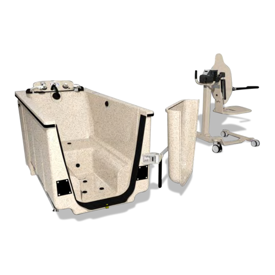
Mastercare MB-80 Maintenance Manual
Integrity bath
Hide thumbs
Also See for MB-80:
- Operating instructions manual (26 pages) ,
- Installation manual (5 pages) ,
- Operation manual (14 pages)

Subscribe to Our Youtube Channel
Related Manuals for Mastercare MB-80


Summary of Contents for Mastercare MB-80
- Page 1 Integrity Bath Model MB-80 Maintenance Manual For All Maintenance Procedures Follow the Directions in this Manual...
-
Page 2: Maintenance Instructions
MAINTENANCE INSTRUCTIONS SCHEDULE MAINTENANCE INSTRUCTIONS Failures of materials can occur due to normal MasterCare bathing systems are purposely designed to wear associated with use over time. Therefore, minimize, as much as possible, the maintenance it is in the best interests of the patient, staff and provider that recommended safety inspections requirements associated with such products. They are... -
Page 3: Quarterly Inspection
Integrity Bath – Model MB-80 Maintenance Manual QUARTERLY INSPECTION: (In addition to the monthly checks Test the ground fault circuit interrupter protecting the following should also be perfo1med quarterly) this appliance periodically in accordance with the manufacturer's instructions. Tub System: Dial thermometer • Aerators • All deficiencies discovered during monthly and Casual water drain •... -
Page 4: Top View
Integrity Bath – Model MB-80 Maintenance Manual DOOR TO SEAL RELATIONSHIP DOOR SEAL INSPECTION/REPLACEMENT SEAL RETAINER SEAL OVER COMPRESSION PROPER DOOR MAY CUT SEAL ON NO COMPRESSION COMPRESSION EDGE RETAINER SEAL LIP AT ANGLE SEAL LIP FLAT a) If seal shows signs of wear or has lost its elasticity replace. b) To replace pull old seal our of space between retainer and tub wall. Lubricate new seal with soap and water and push into place. DOOR CLOSE LATCH UP/DOWN ADJUSTMENT Close Door and push down to lowest position. Remove SET SCREW #1 and loosen SET SCREW #2 both sides. Slide the ALUMINUM MOUNTING BLOCK on the STAINLESS STEEL GUIDE TUBE a) until the PLASTIC WEDGE index is on top of the PLASTIC BUSHING. b) Position ALUMINUM MOUNTING BLOCK to insure even engagement of PLASTIC WEDGE. Check the clearance of the bottom edge of the DOOR. See drawing below. You should have 1/16". If not adjust mount block up to raise door, mounting block down to lower door. Tighten #2 SET SCREWS and cycle door to verify proper locking. Readjust if necessary. After proper adjustment tighten #2 SET SCREWS and #1 SET SCREWS. - Page 5 Integrity Bath – Model MB-80 Maintenance Manual DOOR IN/OUT ADJUSTMENT LOCK Properly adjusted the door will stop just short of the inside NUT tub rails. To adjust, locate the CAP HEAD SCREW that acts as a stop for the door. See item #6 coupled with item #4 on CAP HEAD SCREW drawing #804305. Loosen the LOCK NUT at the base of the screw. Adjust in and out as needed. Lock into place with LOCK NUT. See drawing to the right. DOOR SLIDE END CAP Inspect the SLIDE END CAP item# 3 in drawing# 803966. It should not be worn through on the side that contacts the outer surface of the door. To replace: 1. Remove old end cap. 2. Clean any residual adhesive. 3. Smear a small amount of clear silicone on inside of new cap.
- Page 6 Integrity Bath – Model MB-80 Maintenance Manual TUB SYSTEM Tub Pop-up Drain Stopper Adjustments & Maintenance Drain Brake Adjustment: Reference drawing 800966. Locate both¼ - 20 x 3/8 SS set screws (Item 18) in the bushing • (Item 29) behind the handle flange. Adjust brake tension by slightly tightening both set screws with a 1/8" Allen wrench. Do not over tighten. Tighten just enough to prevent drain pop-up from closing while tub is draining. Drain Pop-Up Stopper Replacement Directions: Reference drawing 800996. Open drain. Back off the SS jam nut •...
- Page 7 Integrity Bath – Model MB-80 Maintenance Manual Blower Motor On/Off Air Switch & Transmitter System Replacement Air Switch Replacement Tub Without Reservoir (Reference drawing 804320): Remove service door on the side the electrical box is located. Unplug tub from wall socket. Remove electrical box cover. Locate the air switch (Item 72). Disconnect the air tubing (Item 79) from the switch nipple. Remove spade connectors from switch terminals, noting which was connected to which terminal. Remove nut holding the switch in place. Install new switch. Reconnect spade connectors and air tubing to switch. Test new switch. Plug tub back into socket then replace the service door. Replace electrical box cover. For tubs with variable speed blower motors, the switch is incorporated inside the panel and can be removed and replaced in the same as the air transmitter after unplugging the power cable from the back. DRAWING of the Blower Motor if available 2071 14 Ave – Columbus, NE 68601 07-06-15 800-798-5867 FAX: 402-563-9102 Page 7 of 16 www.mastercarebath.com...
- Page 8 Integrity Bath – Model MB-80 Maintenance Manual MIXING VALVE CARTRIDGE (ITEM #600578): Note: Read and follow all instructions thoroughly. Refer to the GEN II Mixing Valve Diagram to reference details. Supplies needed: Silicone lubricant if replacing the cartridge (readily available at local hardware stores). Adjustment Instructions: Using a utility knife, gently pry off the cap (6) that is located on top of the thermostatic control valve handle (7). Using a Philips head screwdriver, remove the screw (8) and thermostatic control valve handle (7). Orientation of the setting ring (5). Note: When the two red lines on the side of the cartridge (2) line up the water F. Rotate the setting ring (5) counter clockwise a notch or two to increase the temperature is approximately 100 temperature. Doing so will increase the water temperature to approximately 110...
- Page 9 Integrity Bath – Model MB-80 Maintenance Manual GEN II MIXING VALVE DIAGRAM ITEM NO. DESCRIPTION QTY THERMOSTATIC VALVE CARTRIDGE, REPLACE THERMOSTATIC O-RING HUB SETTING RING CAP HANDLE, ROUND ZINC FOR THERMOSTATIC CONTROL VALVE USE SCREW ESCUTCHEON, BRASS FOR VOLUME 2071 14 Ave – Columbus, NE 68601 07-06-15 800-798-5867 FAX: 402-563-9102 Page 9 of 16 www.mastercarebath.com...
- Page 10 Integrity Bath – Model MB-80 Maintenance Manual AERATION INJECTOR ROUTINE MAINTENANCE CHECK LIST Check area between top of aerator injector body and underside rubber aeration valve. If dirty clean with a "Q" tip. If • heavy build-up of lime on top of injector body, remove aeration valve then sand off with 400 grit wet/dry sand paper. Replace aeration valve. Check rubber on aeration valve. If hard or cracked replace. • Check aeration body tightness against tub floor. If loose tighten until ;'0" ring part# 36000 under the shoulder seals. • With tub full of water and air on, Check area around aeration gasket. If leaking in this area replace the "0" ring part# • 36000 and the gasket part# 35805. Check clear braided hose for signs of moisture. If noticed the check valve part # 35830 has failed. Pull hose off and • replace with new check valve. ITEM NO. PART NUMBER DESCRIPTION QTY 35831 UMBRELLA SMALL 35833 UMBRELLA LARGE (FLURO SILICONE) 36000 O-RING 3/32 x 1-1/4 x 1-7/16 42212 "O" RING, #18, BUNA 50, 3/4 I.D.X7/8 O.D. 568-018 1 804840 UMBRELLA CHECK VALVE BODY 804841 UMBRELLA CHECK VALVE INSERT 2071 14 Ave – Columbus, NE 68601 07-06-15 800-798-5867 FAX: 402-563-9102 Page 10 of 16 www.mastercarebath.com...
- Page 11 Integrity Bath – Model MB-80 Maintenance Manual VARIABLE SPEED BLOWER (ENTREE 500105 ??) 2071 14 Ave – Columbus, NE 68601 07-06-15 800-798-5867 FAX: 402-563-9102 Page 11 of 16 www.mastercarebath.com...
-
Page 12: Dispensing System
Shampoo. Priming Operation: Remove the empty one gallon container of solutions and Caution: Other brand bath oils and shampoos replace with MasterCare's Bath Oil or Shampoo. may be used with the MasterCare System although re-calibration may be required. To prime, push appropriate button for the solution you are However, some products may not be compatible priming for seven seconds. with the system and may damage components SYSTEM DIAGNOSTICS: in the system, thereby voiding the warranty... - Page 13 "0" ting. Lubricate with liquid soap and reassemble. Check the orifice to make sure it's not clogged or blown • back out. Clean or push orifice back into place. If water is sandy use a line strainer ahead of the injector. • Call your MasterCare representative to order a line strainer. Are there lime deposits in the throat of the injector? • Certain chemicals can cause precipitation in the throat of the injector. Let the injector draw a deliming agent through it to remove the deposit. [f deposits are so heavy that injection has ceased it may necessary to remove the injector body from the line and soak it in delimer.
- Page 14 Integrity Bath – Model MB-80 Maintenance Manual CHAIR TRANSFER SYSTEM CHAIR TILT BACK GAS SPRING ADJUSTMENT (SAME DRAWING AS CURRENT MANUAL?? Adjustment: Reference drawing to right. Support chair back with bungee cord to seat bottom or have someone hold in upright position. Remove 3/8-16 lock nut pivot bolt on top gas spring to allow rotation of clevis mount. 3) With clevis slid off mounting boss and chair back with jam nut loosened...
-
Page 15: Scale Calibration
Integrity Bath – Model MB-80 Maintenance Manual SCALE CALIBRATION Memo: Before calibrating acquire a calibrated 25 lb. weight. Note: The weight must calibrated or scale will display inaccurate weights. Chair must be on carder with scale in order to calibrate. Turn the scale on by pushing the ON/ZERO BUTTON. With scale on ensure the lbs display is showing. If not push the LBS/KG BUTTON until lbs. shows on the ·display. - Page 16 Integrity Bath – Model MB-80 Maintenance Manual DRAWINGS/PICTURES 800656 - Integrity Consol Assembly • New drain drawings. Old has 800996 • 803965 - Gas Spring Assembly • Door Handle Assembly (301176 ?) • 804220 - Console Plumbing Assembly • 804221 - Console Plumbing Pre-assembly • 804225 - Reservoir Assembly • 804245 - Drain Shoe Assembly Integrity Reservoir • 804255 - Plumbing Assembly integrity / Do I need the 600941 instead? • 804256 - Plumbing Pre-assembly Non-console • 804305 Door Hinge Assembly • 804320 - Integrity Assembly w/ Console (5 pages) • 804325 - Integrity Assembly Non Console (5 pages) • 803966 - Door Assembly • 804500 - Door Mounting Assembly • 2071 14 Ave – Columbus, NE 68601 07-06-15 800-798-5867 FAX: 402-563-9102 Page 16 of 16 www.mastercarebath.com...
Need help?
Do you have a question about the MB-80 and is the answer not in the manual?
Questions and answers