
Related Manuals for LXNAV V5


Summary of Contents for LXNAV V5
- Page 1 Installation manual Version 2.0 LXNAV d.o.o. • Kidričeva 24a, 3000 Celje, Slovenia • tel +386 592 33 400 fax +386 599 33 522 info@lxnav.com • www.lxnav.com...
-
Page 2: Table Of Contents
V7 Version 2.0 March 2012 Important Notices Limited Warranty Packing Lists Installation Installing the LXNAV V5 Connecting LXNAV V5 Cutout of V5 Ports and Wiring 3.4.1 LXNAV V5 ports 3.4.1.1 Main port 3.4.1.2 Audio port 3.4.2 V5 vario unit wiring... -
Page 3: Important Notices
March 2012 Important Notices The LXNAV V5 system is designed for VFR use only as an aid to prudent navigation. All information is presented for reference only. Terrain, airports and airspace data are provided only as an aid to situation awareness. -
Page 4: Packing Lists
V7 Version 2.0 March 2012 Packing Lists LXNAV V5 (in Metric or Imperial units as specified) • V5 cable • 3mm Phono Jack to RCA adapter • Page 4 of 10... -
Page 5: Installation
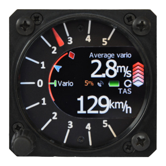
March 2012 Installation The V5 vario unit and any additional vario indicators each require a standard 57 mm cut-out. Three pressure connectors are fitted to the back of the V5 vario unit. A label shows their functions. means static pressure connector. -
Page 6: Installing The Lxnav V5
3.2 Connecting LXNAV V5 LXNAV V57 is connected to main unit through RS485 bus. SC cable is used for external switch, for switching between climb and cruise mode. In case that SC is connected to flaps switch, VP (vario priority) is connected to switch on stick. -
Page 7: Ports And Wiring
V7 Version 2.0 March 2012 3.4 Ports and Wiring Page 7 of 10... -
Page 8: Lxnav V5 Ports
Total pressure probe Static probe TE probe or (Pitot) Static Main port Audio output 3.4.1.1 Main port On main port is connected V5 wiring. 3.4.1.2 Audio port Here is connected speaker with standard 3mm phono jack. Page 8 of 10... -
Page 9: V5 Vario Unit Wiring
LABEL:OAT GND SHIELD V5 has four additional inputs comparing to the old vario systems. Those inputs can be connected to Eg. Gear, Airbrake switches, which can be set in setup-hardware-variometer. There is also CAN bus connector, which is prepared for future. - Page 10 Select appropriate update file and wait until update will finish. V5 update consist ot two firmwares (SBOX and VIND). SBOX updates sensoric part of V5, VIND updates display part of V5 Page 10 of 10...
Need help?
Do you have a question about the V5 and is the answer not in the manual?
Questions and answers